
Reinforced inner support structure for refrigeration compressor

A refrigeration compressor and support structure technology, applied in mechanical equipment, machines/engines, liquid fuel engines, etc., can solve problems such as increased clearance, unstable electrical air gaps in operation, and serious friction between rotor and stator parts. The effect of reducing electrical air gap, improving performance and reducing frictional resistance

Inactive Publication Date: 2017-01-25
黄石艾博科技发展有限公司
View PDF6 Cites 4 Cited by
  • Summary
  • Abstract
  • Description
  • Claims
  • Application Information

AI Technical Summary

Problems solved by technology

[0004] The purpose of the present invention is to solve the problem that the crankshaft and the rotor assembly in the existing compressor are supported and positioned by a single point cantilever, the friction between the rotor and the stator is serious, the gap increases, and the running electrical air gap is unstable, etc., to provide a refrigeration compressor Strengthen the inner support structure

Method used


Image

  • Reinforced inner support structure for refrigeration compressor
  • Reinforced inner support structure for refrigeration compressor
  • Reinforced inner support structure for refrigeration compressor

Examples


Embodiment Construction

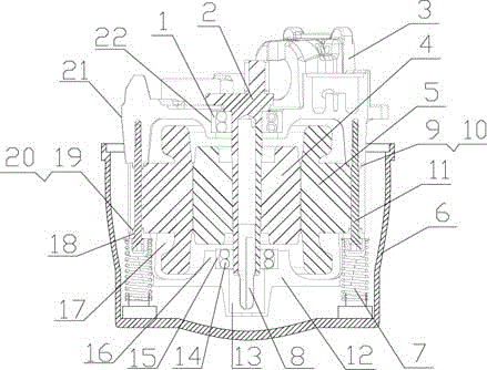
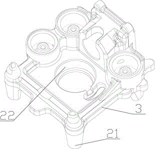
[0019] see figure 2 , a reinforced internal support structure of a refrigeration compressor in the present invention, including a housing 6, a stator 5 installed in the housing 6, a rotor 4, a cylinder block 3 installed above the stator 5, and a cylinder block 3 mounted on the rotor The crankshaft 2 between 4, the lower end of the crankshaft 2 is equipped with an oil suction pipe assembly 8, and the middle part of the cylinder block 3 is provided with a counterbore 22 to install the bearing A1 to form a rotational support for the upper end of the crankshaft 2, especially: a bracket is added below the stator 5 12. Left and right bolt holes 18 are provided on the bracket 12, and the bolt holes 18 on the bracket 12 and the bolt holes 18 on the stator 5 are threadedly connected with the cylinder block 3 through the bolt 11, and the bracket 12, the stator 5, the cylinder The seat 3 is installed as a whole; the middle part of the bracket 12 is provided with a boss 16, the upper par...


PUM


Abstract

The invention relates to an improvement technology of a refrigeration compressor, in particular to a reinforced inner support structure for the refrigeration compressor. The reinforced inner support structure for the refrigeration compressor comprises a stator, a rotor, a cylinder base mounted above the stator and a crankshaft inserted between the cylinder base and the rotor; a counter bore is formed in the middle part of the cylinder base; a bearing A is mounted to form rotational bearing for the upper end of the crankshaft. The reinforced inner support structure for the refrigeration compressor is characterized in that a bracket is additionally arranged below the stator; left and right bolt holes are formed in the bracket, and the bracket is in threaded connection with the cylinder base by enabling bolts to pass through the bolt holes in the bracket and bolt holes in the stator; a boss is formed at the middle part of the bracket; a bearing hole is formed in the upper part of the boss for mounting a bearing B; an oil suction pipe assembly vortex cavity is formed in the lower part of the boss; the bearing B and the lower end of the crankshaft are assembled to form a rotational bearing. The reinforced inner support structure for the refrigeration compressor, which is disclosed by the invention, solves the problems of low working efficiency of an existing compressor and the like, which are caused by the case that a crankshaft and rotor assembly is supported and positioned by a stator inner hole and a single-point cantilever, the compressor works unstably, a gap between a stator and a rotor is large and an operation electrical air gap is unstable, and is mainly applicable to refrigeration equipment such as a refrigerator, a freezer and the like.

Description

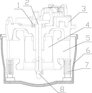
technical field [0001] The invention relates to an improvement technology of a refrigeration compressor, in particular to a reinforced internal support structure of a refrigeration compressor. Background technique [0002] Refrigeration compressors are the core components of refrigerators and freezers. The energy efficiency of the compressor is directly related to the energy efficiency level of the refrigerator. The air gap size of the stator and rotor of the compressor is closely related to the energy efficiency of the compressor. The compressor is mainly composed of bearing A1, crankshaft 2, cylinder block 3. Composed of rotor 4, stator 5, housing 6, damping spring 7, and oil suction pipe assembly 8, the current supporting method of compressor stator and rotor is as follows: figure 1 Shown: It is mainly composed of the four installation and positioning columns of the cylinder block and the upper end surface of the stator, which are screwed together with the screws and gask...

Claims


Application Information

Patent Timeline
Patent Type & Authority Applications(China)
IPC IPC(8): F04C29/00F04C29/02
CPCF04C29/00F04C29/02F04C2240/10F04C2240/50
Inventor 龚艳雄林军李景锋蔡少南谢良和杨涛夏文杰
Owner 黄石艾博科技发展有限公司
Learn More