Cable terminal tightening device

A fastening device and cable terminal technology, which is applied in the direction of cable suspension device, cable installation, electrical components, etc., can solve the problems of falling off, difficult operation, large randomness, etc., and achieve simple structure, good firmness, and easy to use convenient effect

Active Publication Date: 2017-01-25
GUANGZHOU PANYU CABLE WORKS
View PDF7 Cites 13 Cited by
  • Summary
  • Abstract
  • Description
  • Claims
  • Application Information

AI Technical Summary

Problems solved by technology

[0002] It is very important to ensure the safe and stable operation of the power grid in today's society. The cable is erected on the pole or building through the street code. The cable end is generally fixed by bending the cable end around the terminal street code and then In the tensioned state, use metal wires or other fixing devices to bind or fix the cable ends; at present, construction workers usually use traditional methods such as manpower or simple tools to bend the cable ends and make the cable ends in a tensioned state The cable ends are bound and fixed with metal wires. Due to the thicker diameter of the cables with large currents, it is difficult to use the traditional metal wire binding method to operate, and there is no uniform standard for the binding method, which is very random, resulting in cable ends. The firmness of the binding is difficult to guarantee, and the cable end is easy to loosen and fall off the street yard, which brings safety hazards

Method used


Image

  • Cable terminal tightening device
  • Cable terminal tightening device

Examples


Embodiment 1

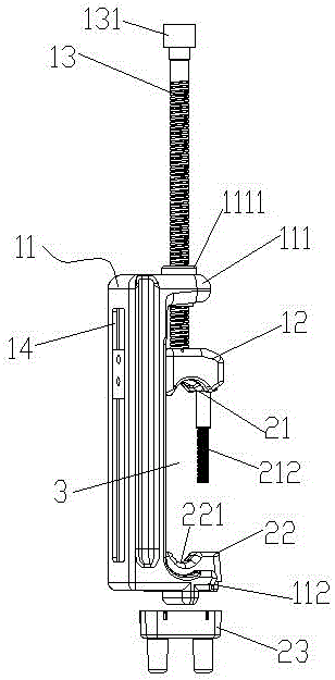
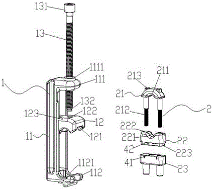
[0033] Such as Figure 1-2As shown, a cable terminal fastening device includes a fastening device 1 and a fastening clamp 2. The fastening device 1 includes a crimping body 11, a dynamic pressure block 12 and a crimping screw 13. The crimping body 11 includes oppositely arranged The connection part 111 and the support part 112, the compression screw 13 is threadedly connected with the connection part 111, one end of the compression screw 13 is rotatably connected with the dynamic pressure block 12, and the other end is provided with a rotating part 131, and the dynamic pressure block 12 is located at Between the connecting part 111 and the supporting part 112 and opposite to the supporting part 112, the crimping body 11 is provided with a function to limit the dynamic pressure block 12 to only perform linear reciprocating movement between the connecting part 111 and the supporting part 112 and cannot rotate. The limit mechanism can adjust the linear movement of the dynamic pre...


PUM


Abstract

The invention discloses a cable terminal tightening device. The cable terminal tightening device comprises a tightening device and a tightening wire clip, wherein the tightening device comprises a wire pressing body, a movable press block and a pressing screw rod; the wire pressing body comprises a connecting part and a support part; the movable press block is arranged between the connecting part and the support part through the pressing screw rod and is only performed with the linear movement between the connecting part and the support part; the tightening wire clip comprises a male clip, a female clip and a locking device; the male clip and the female clip are tightly matched with the movable press block and the support part; in the use process, a bent cable terminal is arranged between the male clip and the female clip, and then the pressing screw rod is rotated to enable the movable press block to move relative to the support part until the cable is pressed under the matching action of the male clip and the female clip; the male clip, the cable and the female clip are locked together through the locking device; finally, the pressing rod is reversely rotated to disengage the tightening wire clip from the tightening device. The cable terminal tightening device has the advantages that the cable terminal can be quickly tightened, the fixing efficiency of the cable terminal is greatly improved, the firmness is good, the structure is simple, and the universality is good.

Description

technical field [0001] The invention relates to the field of power tools, in particular to a cable terminal fastening device. Background technique [0002] It is very important to ensure the safe and stable operation of the power grid in today's society. The cable is erected on the pole or building through the street code. The cable end is generally fixed by bending the cable end around the terminal street code and then In the tensioned state, use metal wires or other fixing devices to bind or fix the cable ends; at present, construction workers usually use traditional methods such as manpower or simple tools to bend the cable ends and make the cable ends in a tensioned state The cable ends are bound and fixed with metal wires. Due to the thicker diameter of the cables with large currents, it is difficult to use the traditional metal wire binding method to operate, and there is no uniform standard for the binding method, which is very random, resulting in cable ends. The fi...

Claims


Application Information

Patent Timeline
Patent Type & Authority Applications(China)
IPC IPC(8): H02G7/05
CPCH02G7/056
Inventor 胡超强尤占山王延发覃丹卢广业张仕欢陈雪儿郝燕张开拓易坡杜小建程雪丽
Owner GUANGZHOU PANYU CABLE WORKS
Why Eureka
Try Eureka