
Temperature measuring device and measuring method for thermal analyzer

A technology of temperature measurement and thermal analyzer, applied in the direction of electric radiation detectors, etc., can solve the problems of not being able to obtain the overall temperature of the thermal analysis instrument and the interference of the measured temperature, and achieve the effect of not affecting the temperature field distribution and high measurement accuracy

Pending Publication Date: 2017-02-01
BEIJING INFORMATION SCI & TECH UNIV
View PDF0 Cites 1 Cited by
  • Summary
  • Abstract
  • Description
  • Claims
  • Application Information

AI Technical Summary

Problems solved by technology

[0003] In the temperature measurement of the existing thermal analysis instruments, the thermocouple temperature measurement method is mainly used. This method is a contact temperature measurement method, which can measure the temperature value required for the experiment. However, it also has a contact method. Disadvantages of temperature measurement - the measurement is the equilibrium temperature of the measured object and the sensor, which will interfere with the measured temperature when measuring
In addition, this method can only obtain the temperature at one point, and cannot obtain the overall temperature in the thermal analysis instrument.

Method used


Image

  • Temperature measuring device and measuring method for thermal analyzer
  • Temperature measuring device and measuring method for thermal analyzer
  • Temperature measuring device and measuring method for thermal analyzer

Examples


Embodiment

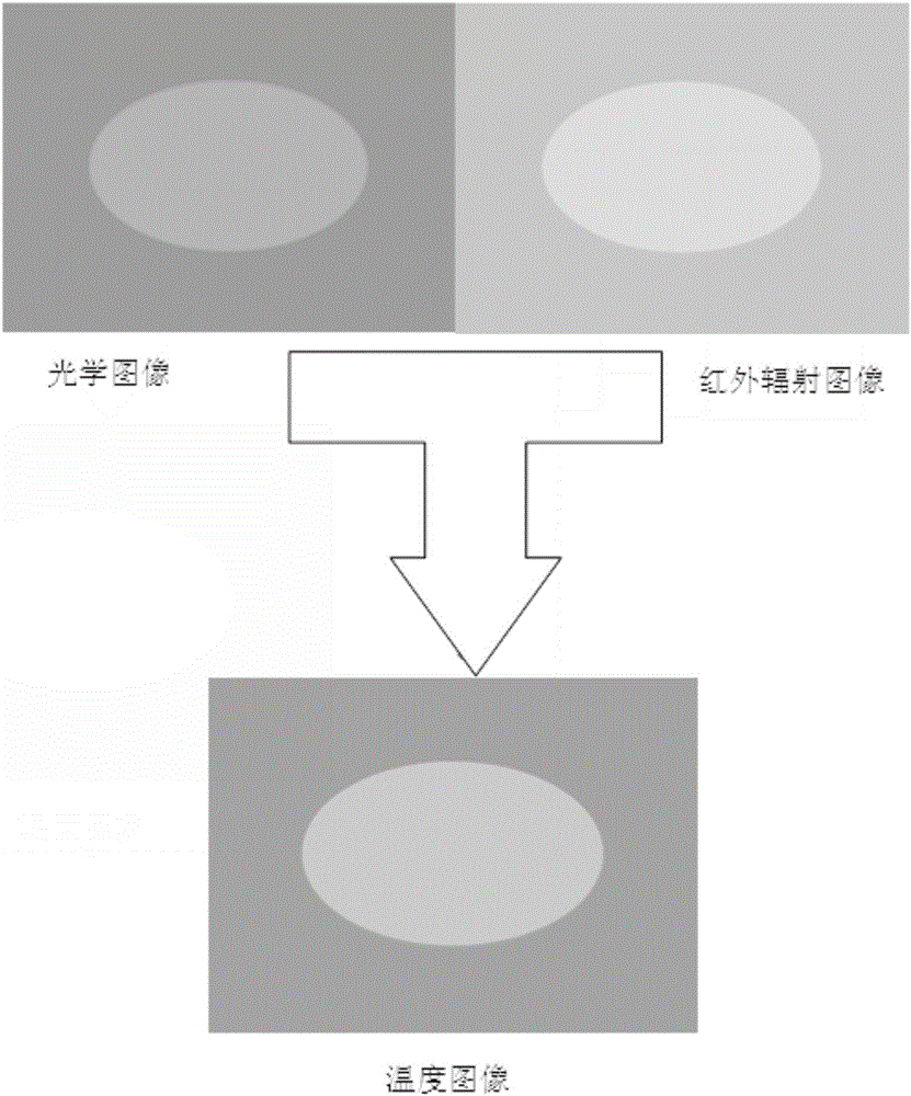
[0053] The color fusion image finally obtained by the present invention includes both infrared radiation information in the heating furnace and optical information, that is, two main electromagnetic waves radiated during the heating process. It can well characterize the temperature condition in the furnace. For example, if image 3 As shown, when the temperature is low, the infrared image is obtained, the middle ellipse is yellow, and the surrounding is orange, and different colors represent different temperatures. When the temperature rises, the radiated electromagnetic waves are mainly displayed in the form of visible light. In the obtained optical image, the middle ellipse and the surrounding area are red and orange respectively. The inner wall of the furnace heated to a certain temperature can be regarded as a light source. Different colors reflect different temperature. In the fused image, the part with high temperature is displayed in red tone, and the part with low te...


PUM


Abstract

The invention relates to a temperature measuring device and measuring method for a thermal analyzer. The method comprises: a sensor array for absorbing infrared radiation energy and an image sensor are arranged inside a sealed heating furnace, the sensor array transmits a collected infrared radiation signal to a signal processor to form infrared thermogram information and transmits the information to a computer; the image sensor arranged inside the sealed heating furnace transmits collected image information inside the heating furnace to the computer by an acquisition card; and the computer carries out information fusion processing on the received infrared thermogram information and the image information collected by the image sensor to obtain new temperature data, and the temperature distribution situation inside the heating furnace is displayed based on the new temperature data. According to the invention, a defect caused by contact type temperature measuring is overcome; and the temperature environment can be measured precisely and the temperature measuring range can be extended. The temperature measuring device and measuring method can be widely applied to temperature measuring of an overall temperature filed in sealed vacuum space, especially to a vacuum occasion needing precise measurement of the overall environment temperature.

Description

technical field [0001] The invention relates to a temperature measuring device and a measuring method, in particular to a temperature measuring device and a measuring method for a thermal analyzer used in measuring the overall temperature field of a closed vacuum space. Background technique [0002] There are two types of temperature measurement technology, contact and non-contact. Contact temperature measurement methods include expansion temperature measurement, electric quantity temperature measurement, contact photoelectric temperature measurement, and thermochromic temperature measurement. The contact temperature measurement method needs to be in full contact with the measured object or medium during measurement. Generally, it measures the equilibrium temperature of the measured object and the sensor, which will interfere with the measured temperature to a certain extent. The non-contact temperature measurement method does not need to be in contact with the measured obj...

Claims


Application Information

Patent Timeline
IPC IPC(8): G01J5/10
CPCG01J5/10Y02E30/30
Inventor 吴国新石守娟徐小力左云波
Owner BEIJING INFORMATION SCI & TECH UNIV
Learn More