Supercharge Your Innovation With Domain-Expert AI Agents!

Tag antenna and tag

A tag antenna and tag technology, applied in the field of radio frequency, can solve the problem of short recognition distance of human body surface and achieve high gain effect

Active Publication Date: 2017-02-01
ZHEJIANG JOHAR TECH CO LTD
View PDF5 Cites 0 Cited by
  • Summary
  • Abstract
  • Description
  • Claims
  • Application Information

AI Technical Summary

Problems solved by technology

[0007] In order to overcome the problem that the existing RFID tags are applied to the human body surface with a short recognition distance, the present invention provides a tag antenna and a tag with a large recognition distance both on the human body surface and in free space.

Method used


Image

  • Tag antenna and tag
  • Tag antenna and tag
  • Tag antenna and tag

Examples


Embodiment Construction

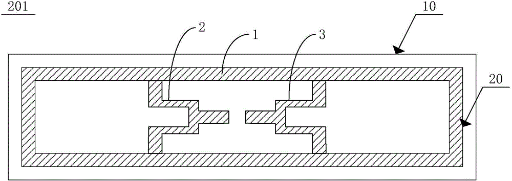
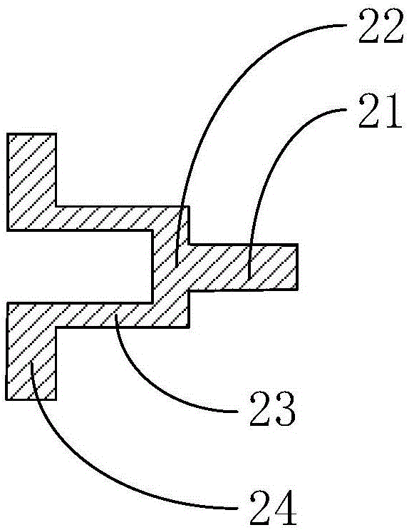
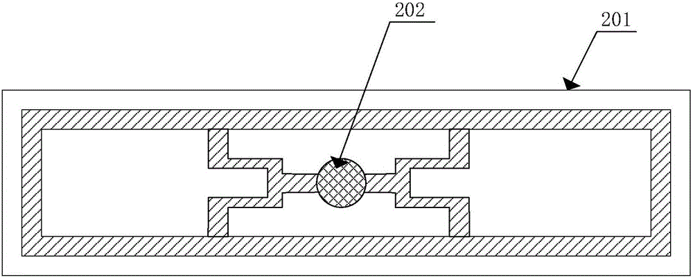
[0030] figure 1 Shown is a schematic structural diagram of a tag antenna provided by an embodiment of the present invention. figure 2 shown as figure 1 An enlarged view of the second substructure in . image 3 Shown is a schematic structural diagram of a label provided by an embodiment of the present invention. Figure 4 shown as image 3 Schematic diagram of the structure of the label when it is applied to the body surface of a human body. Figure 5 Shown is the input impedance diagram when the tag provided by the present invention is placed in free space and on the surface of a human body. Image 6 Shown is the gain pattern of the tags provided by the present invention placed in free space. Figure 7 Shown is the gain pattern when the tag provided by the present invention is placed on the human body surface. Figure 8 Shown is the return loss diagram when the tag provided by the present invention is placed in free space and on the surface of a human body. Please also...


PUM


Abstract

The invention provides a tag antenna and a tag. The tag antenna comprises a substrate and an antenna pattern formed on the substrate, wherein the antenna pattern comprises a first sub structure, a second sub structure and a third sub structure; the first sub structure adopts a sealed annular shape; the second sub structure and the third sub structure are the same in structure and are symmetrically arranged in the first sub structure; the second sub structure and the third sub structure are connected with the first sub structure separately; and the first sub structure, and the second sub structure and the third sub structure form the sealed shape.

Description

technical field [0001] The invention relates to the field of radio frequency technology, and in particular to a tag antenna and a tag. Background technique [0002] At present, passive UHF RFID technology is widely used in various industries, such as personnel management, cold chain transportation and other industries. In some application backgrounds, such as personnel management, it is necessary to attach RFID tags to the human body, so in many occasions, it is necessary to design a special tag antenna for the application of the human body surface. [0003] Under free space conditions, the recognition distance between the RFID reader and the RFID tag is determined by the following formula: [0004] R = λ 4 π E I R P * G t a g ...

Claims


Application Information

Patent Timeline
Patent Type & Authority Applications(China)
IPC IPC(8): H01Q1/22H01Q1/38H01Q1/50H01Q7/00
CPCH01Q1/2225H01Q1/38H01Q1/50H01Q7/00
Inventor 季宏红林生洲
Owner ZHEJIANG JOHAR TECH CO LTD
Features
  • R&D
  • Intellectual Property
  • Life Sciences
  • Materials
  • Tech Scout
  • Unparalleled Data Quality
  • Higher Quality Content
  • 60% Fewer Hallucinations
Learn More