Supercharge Your Innovation With Domain-Expert AI Agents!

Miniature LED display array and display screen

A display array and miniature technology, which is applied in the direction of instruments, identification devices, etc., can solve the problems of reducing the screen ratio, increasing the display frame, and uneven voltage drop of pixel units, so as to achieve the reduction of voltage drop difference and impedance difference. Small, to improve the effect of the display effect

Pending Publication Date: 2022-04-22
JIHUA LAB
View PDF7 Cites 1 Cited by
  • Summary
  • Abstract
  • Description
  • Claims
  • Application Information

AI Technical Summary

Problems solved by technology

[0003] figure 1 It is a schematic structural diagram of a micro-LED display in the related art, such as figure 1 As shown, in the related art, a cathode ring is usually set around the middle display area of ​​the micro-LED display. Since the pixel units at different positions in the middle display area are different from the surrounding cathode rings, the pixel units close to the cathode ring have corresponding The cathode metal impedance is relatively small, so the voltage drop is small; while the pixel unit far away from the cathode ring has a relatively large cathode metal impedance, so the voltage drop is relatively large; thus, the voltage drop of each pixel unit in the display area is uneven. In this case, the voltage applied to both ends of the pixels in the display area shows a general trend of small middle position and large edge position, which will lead to the abnormal brightness of the display screen with low brightness in the middle position and high brightness at the edge position, and the overall brightness of the display screen Poor uniformity
At the same time, the cathode ring around the display area will increase the display frame and reduce the screen ratio, that is, the ratio of the display area to the total area of ​​the display, reducing the display effect
Furthermore, if multiple display screens are to be spliced ​​together to form a larger display screen to display pictures or videos collaboratively, the large-frame display screen will cause obvious seams at the splicing area, which will affect the display effect

Method used


Image

  • Miniature LED display array and display screen
  • Miniature LED display array and display screen
  • Miniature LED display array and display screen

Examples


Embodiment Construction

[0042] In order to more clearly understand the above objects, features and advantages of the present disclosure, the solutions of the present disclosure will be further described below. It should be noted that, in the case of no conflict, the embodiments of the present disclosure and the features in the embodiments can be combined with each other.

[0043] In the following description, many specific details are set forth in order to fully understand the present disclosure, but the present disclosure can also be implemented in other ways than described here; obviously, the embodiments in the description are only some of the embodiments of the present disclosure, and Not all examples.

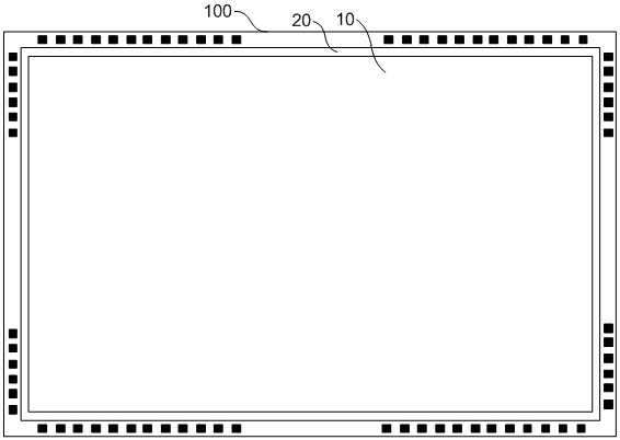
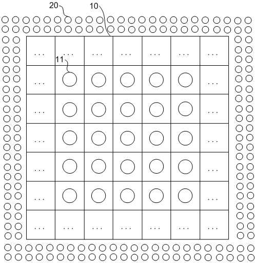
[0044] Combined with background technology, such as Figure 1-Figure 2 as shown, figure 2 for figure 1 A schematic diagram of a partially enlarged structure of the micro-LED display shown. In the related art, a cathode ring 20 is usually arranged around the display area 10 in the middle of t...


PUM


Abstract

The invention relates to a miniature LED display array and a display screen in the technical field of light-emitting display. The display array comprises a first electrode and a second electrode, the pixel units are arranged on one side of the first electrode and are arranged in an array; the second electrode is arranged on one side, deviating from the first electrode, of the pixel unit; the second electrodes and the pixel units are arranged in a one-to-one correspondence manner; the at least two auxiliary electrodes and the pixel units are arranged on the same side of the first electrode; the auxiliary electrode is electrically connected with the first electrode; the auxiliary electrodes are uniformly distributed in the pixel unit array, and gaps exist between the auxiliary electrodes and the pixel units; wherein the first electrode and the second electrode are respectively one of an anode and a cathode. The auxiliary electrodes are arranged in the pixel unit array, so that the distance from the pixel units to the auxiliary electrodes is shortened, the impedance difference value of the pixel units at the middle and edge positions is reduced, the voltage drop difference value is also reduced, and the uniformity of display brightness is improved; and no cathode ring exists, the frame and the splicing gap are narrowed, and the screen-to-body ratio and the display effect are improved.

Description

technical field [0001] The present disclosure relates to the technical field of light-emitting display, in particular to a micro-LED display array and a display screen. Background technique [0002] Micro Light Emitting Diode (Micro-LED) displays are superior in many ways to the currently used Liquid Crystal Display (LCD) and Organic Light Emitting Diode (OLED) displays, Such as thinner screen body, higher efficiency, longer life, higher brightness, and faster response speed, etc., so micro-LED displays have received more and more attention. [0003] figure 1 It is a schematic structural diagram of a micro-LED display in the related art, such as figure 1 As shown, in the related art, a cathode ring is usually set around the middle display area of ​​the micro-LED display. Since the pixel units at different positions in the middle display area are different from the surrounding cathode rings, the pixel units close to the cathode ring have corresponding The cathode metal imp...

Claims


Application Information

Patent Timeline
Patent Type & Authority Applications(China)
IPC IPC(8): G09F9/33
CPCG09F9/33
Inventor 蔡世星岳大川林立谢峰籍亚男
Owner JIHUA LAB
Features
  • R&D
  • Intellectual Property
  • Life Sciences
  • Materials
  • Tech Scout
  • Unparalleled Data Quality
  • Higher Quality Content
  • 60% Fewer Hallucinations
Learn More