Optical grating counterpoint splicing method

A grating and bar graph technology, applied in the field of optics, can solve problems such as large errors

Active Publication Date: 2012-07-04
NINGBO VISION DISPLAY TECH
View PDF4 Cites 12 Cited by
  • Summary
  • Abstract
  • Description
  • Claims
  • Application Information

AI Technical Summary

Problems solved by technology

[0005] The purpose of the present invention is to solve the problem of large errors in the existing method of s...

Method used


Image

  • Optical grating counterpoint splicing method
  • Optical grating counterpoint splicing method
  • Optical grating counterpoint splicing method

Examples


specific Embodiment approach 1

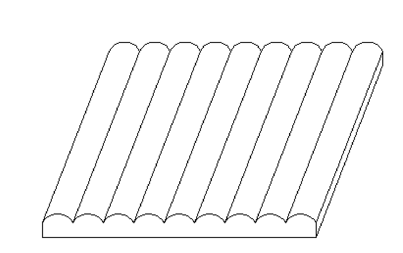
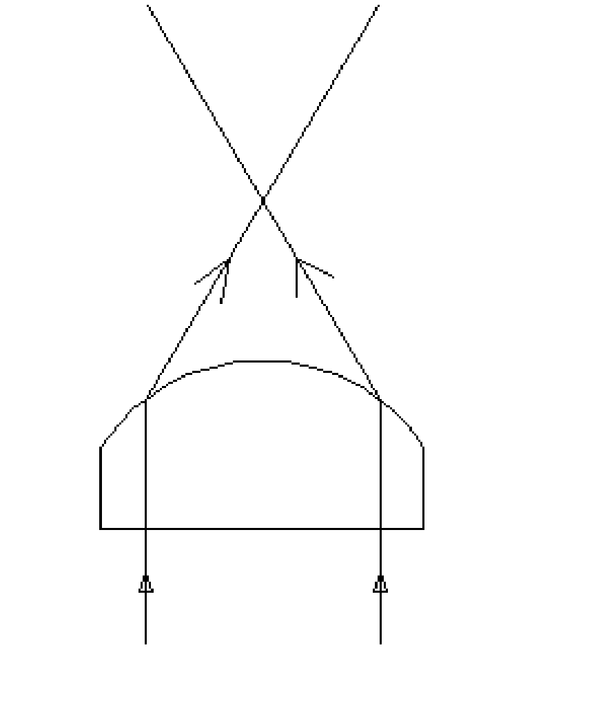
[0021] Specific implementation mode one: the following combination Figure 7 to Figure 10 Describe this embodiment mode, a grating alignment splicing method described in this embodiment, the method is: place n pieces of gratings to be spliced ​​together on the test bar chart, use one of the gratings as a reference grating, and the test bar A graphic pattern forms a reference interference fringe on the reference grating,

[0022] Move and rotate other n-1 pieces of gratings to be spliced ​​separately, so that the test bar graph forms spliced ​​interference fringes on other n-1 gratings to be spliced. When all spliced ​​interference fringes are consistent with the thickness of the reference interference fringes, and When the extension line of the spliced ​​interference fringe and the extension line of the reference interference fringe at the corresponding position are on the same straight line, the alignment splicing of n pieces of grating is completed.

[0023] Wherein, n is a...

specific Embodiment approach 2

[0026] Embodiment 2: In this embodiment, Embodiment 1 is further described. The grating is a ruled optical device or a twill optical device cut at a fixed angle.

specific Embodiment approach 3

[0027] Embodiment 3: In this embodiment, Embodiment 1 is further described. The grating is a plano-convex grating, a biconvex lens grating or a combined lens grating with a lens function.


PUM


Abstract

An optical grating counterpoint splicing method belongs to the field of optics and aims at solving the problem that errors are large by an existing method that two lenticular lens optical gratings are spliced by the aid of a concave optical grating. The optical grating counterpoint splicing method comprises the steps of jointly placing n optical gratings to be spliced on a testing bar chart, using one of n optical gratings as a standard optical grating, and enabling the testing bar chart to form a standard interference fringe on the standard optical grating, respectively moving and revolving n-1 optical gratings to be spliced to enable the testing bar chart to form splicing interference fringes on the n-1 optical gratings to be spliced, and finishing counterpoint splicing of the n optical gratings when all the splicing interference fringes are identical to the standard optical grating in thickness degree and extended lines of the splicing interference fringes and an extended line of the standard optical grating are located in the same straight line. The optical grating counterpoint splicing method is used for splicing a plurality of optical gratings.

Description

technical field [0001] The invention relates to a grating alignment splicing method, which belongs to the field of optics. Background technique [0002] TVs have gone through the display development process from black and white to color, and color to high-definition. Restoring reality is the goal that people have been pursuing. 3D display is recognized as the next generation display technology. Glasses-free 3D technology without wearing any auxiliary equipment has become the focus of attention. At present, the cylindrical lens grating and the slit grating are the main optical devices used in the 3D display industry. The cylindrical lens grating or the slit grating is placed in an appropriate position in front of the TV panel to combine with proper 3D image mixing, or placed with 3D interlaced information On the printout medium, people can enjoy the 3D effect of being in a wonderland and realistic pictures. Among them, the cylindrical lens grating uses the principle of ligh...

Claims


Application Information

Patent Timeline
IPC IPC(8): G02B5/18
Inventor 魏厚伟高洪跃
Owner NINGBO VISION DISPLAY TECH
Why Eureka
Try Eureka