
High speed electronic data transmission system

a transmission system and high-speed technology, applied in data switching networks, logic circuit coupling/interface arrangements, pulse techniques, etc., can solve the problems of high cost of fibre-optic transceivers, inability to convey electrical power, splicing of fibre-optic cables, etc., and achieve cost-effective high-speed effects

Active Publication Date: 2009-06-25
NEW DAY INVESTMENT
View PDF12 Cites 15 Cited by
  • Summary
  • Abstract
  • Description
  • Claims
  • Application Information

AI Technical Summary

Benefits of technology

[0016]The present invention can convey high bandwidth data at a rate comparable to that of fibre-optic systems, yet has the cost advantage and ease of splicing advantage of LVDS systems without susceptibility to signal degradation to which the latter is prone. Furthermore, the present system can carry electrical power in addition to data transmission.

Problems solved by technology

However, due to high costs of fibre-optic transceivers, the difficulty of splicing fibre-optic cables and the inability to convey electrical power in addition to data signals, fibre-optic networks have not extended the whole way to each end-connection point such as home or office modems, telephones or pay-TV receivers.
Although LVDS transmission has replaced single-ended signalling transmission as it provides a higher data transfer rate and better resistance to electromagnetic interference, LVDS systems remain susceptible to electromagnetic interference and signal degradation over extended cable lengths.

Method used


Image

  • High speed electronic data transmission system
  • High speed electronic data transmission system
  • High speed electronic data transmission system

Examples


Embodiment Construction

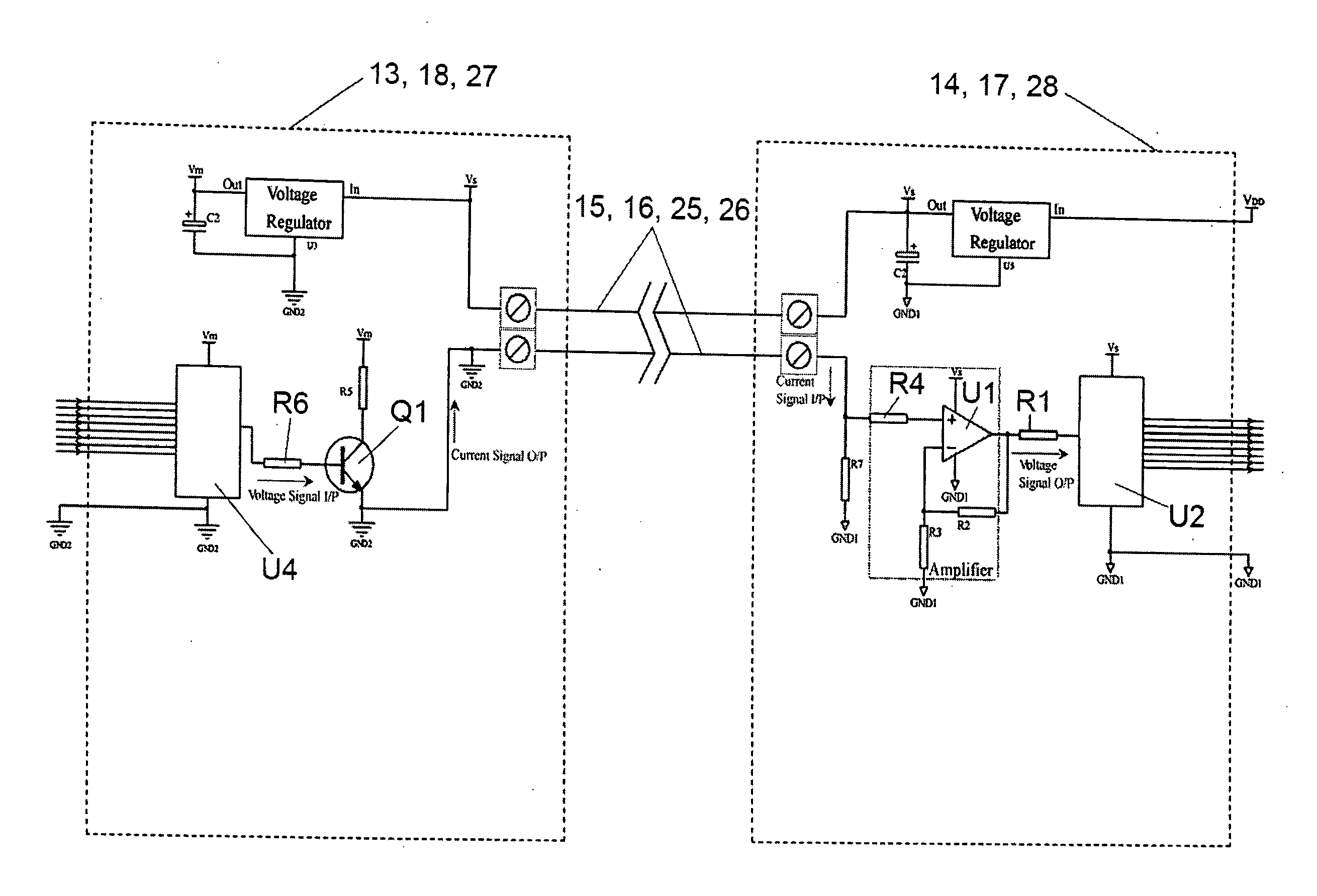
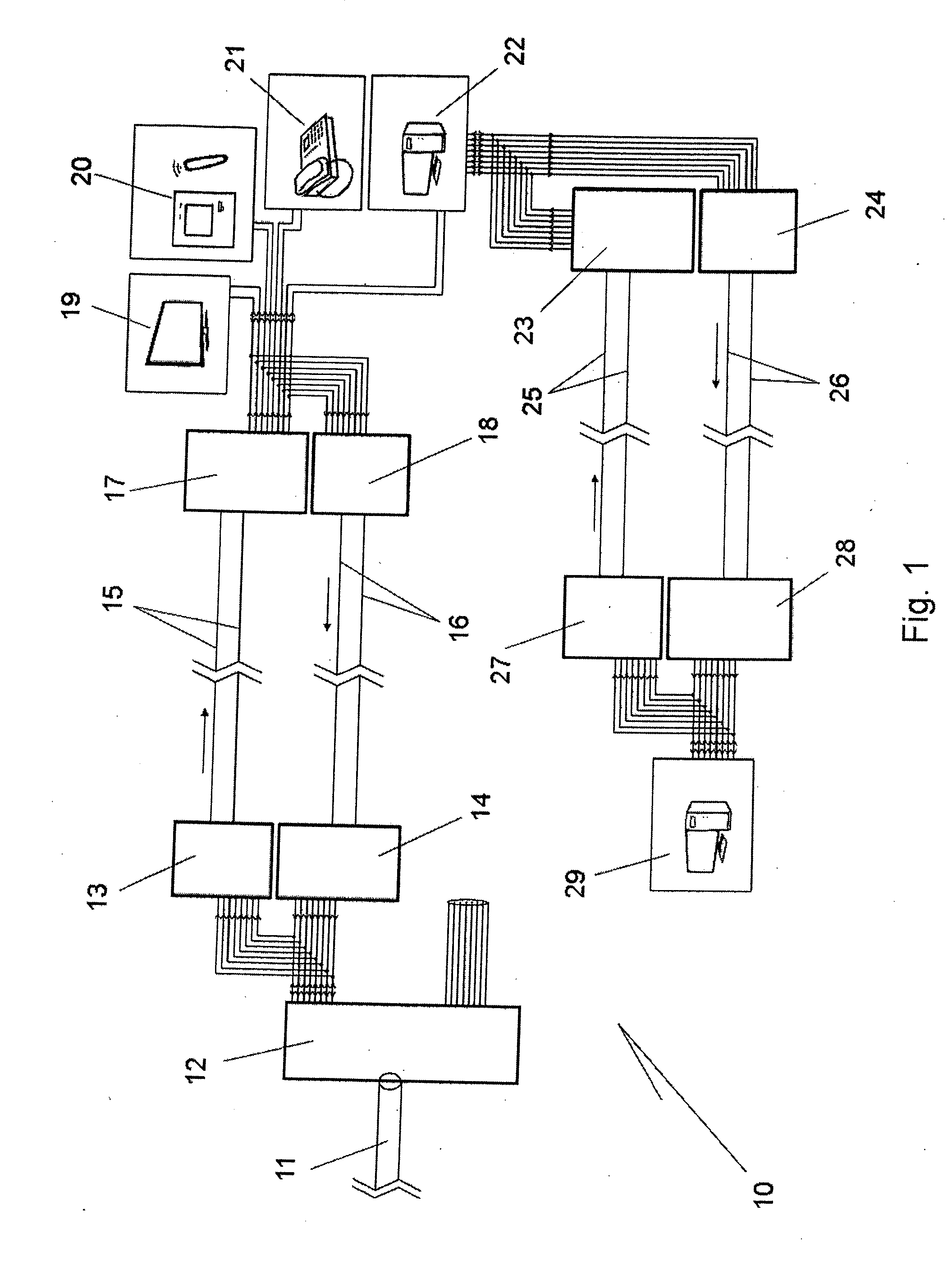
[0023]The block diagram of FIG. 1 depicts high-speed electrical data transmission system 10 communicating data between a fibre-optic public cable network 11 and a home or office local area network including for example a cable television receiver 19, home automation appliances 20, a telephone 21 and a personal computer 22. Of course some of these features could be omitted and others added. In an office local area network, the various components might include a computer server, numerous workstations, photocopiers, fax machines and the like.

[0024]The fibre-optic cable 11 would typically extend under the street or footpath and service numerous offices and / or premises. At each residence or office building for example, there is provided a fibre-optic transceiver 12 which converts optical data signals into electrical data signals.

[0025]Connected electrically to the transceiver 12 is a signal mixer 13 and signal processor 14. A two-conductor cable or “transmission line”15 extends from the ...


PUM


Abstract

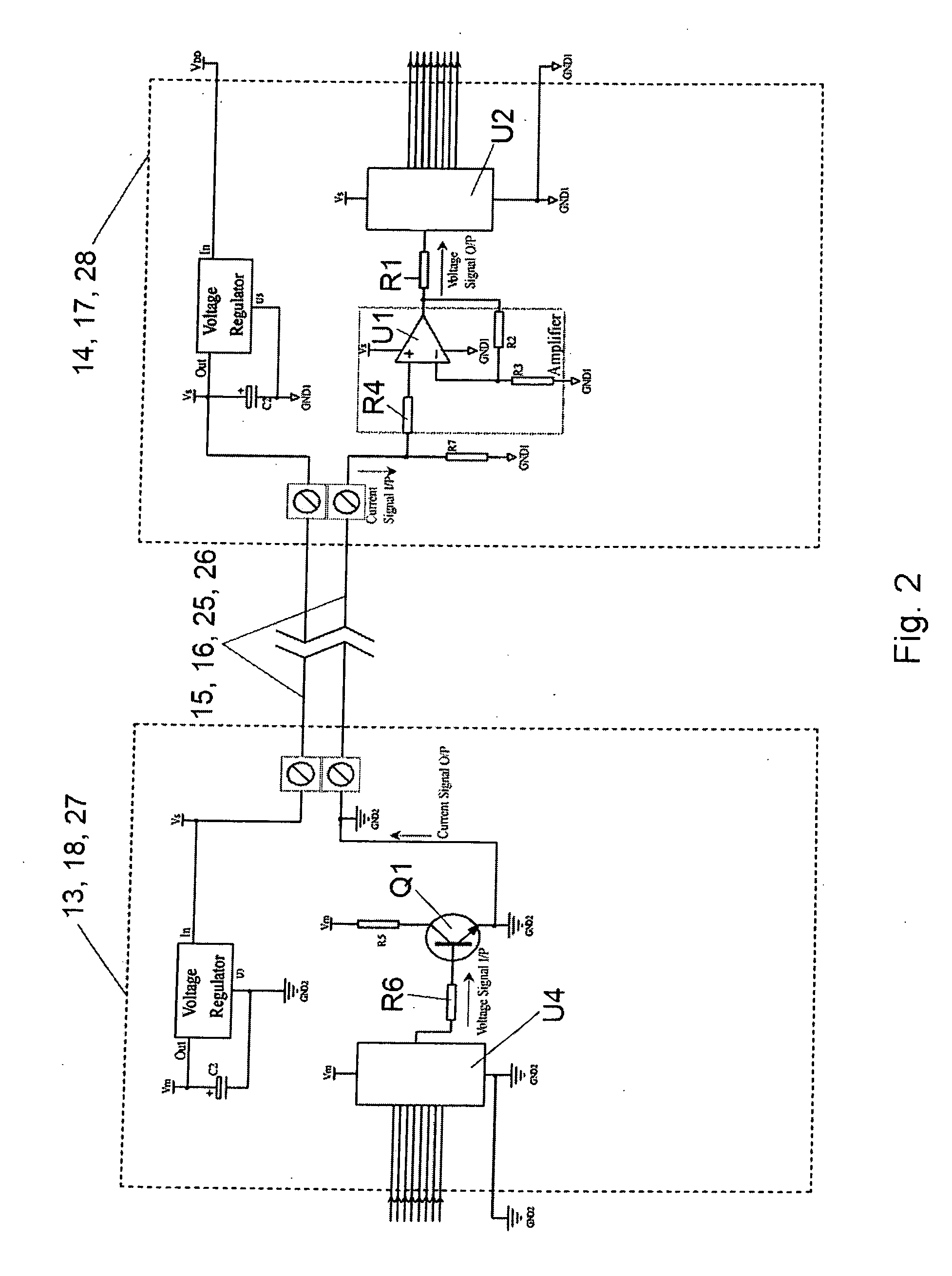
A high-speed electrical data transmission system (10) includes a signal mixer (13) for receiving high-speed data from external network transceiver (12). The signal mixer (13) converts the data into an electrical current-fluctuating data signal. A signal processor (17) is located remotely of the signal mixer (13) and is connected electrically thereto by a simple / inexpensive cable (15) having only two operative conductors and receives the current-fluctuating data signal via the cable (15). The signal processor (17) converts the current-fluctuating data signal into a voltage-fluctuating data signal for distribution to a local area network.

Description

BACKGROUND OF THE INVENTION[0001]The present invention relates to a high-speed electrical data transmission system. The invention relates more particularly, although not exclusively, to a cost-effective system for electrically transmitting data in local area computer networks and other communications networks.[0002]Modern methods of transmitting data signals by cable include fibre-optic communication, Low Voltage Differential Signalling (LVDS) and single ended signalling.[0003]Fibre-optic systems are presently used to achieve high-speed data transmission over long distances. For example, high-speed broadband Internet and pay-TV networks and telephone networks have employed this technology. However, due to high costs of fibre-optic transceivers, the difficulty of splicing fibre-optic cables and the inability to convey electrical power in addition to data signals, fibre-optic networks have not extended the whole way to each end-connection point such as home or office modems, telephone...

Claims


Application Information

Patent Timeline
IPC IPC(8): H03K19/0175
CPCH04L25/0272H04L25/0294H04L25/0282
Inventor LEE, JOHN KAM HO
Owner NEW DAY INVESTMENT
Learn More