
Light field display control method and device, and light field display equipment

A display control method and technology of display equipment, which are applied in the directions of image reproducers, picture reproducers, and televisions using projection devices, and can solve the problems of low spatial resolution and sacrificing display resolution.

Active Publication Date: 2017-02-01
BEIJING ZHIGU RUI TUO TECH
View PDF4 Cites 6 Cited by
  • Summary
  • Abstract
  • Description
  • Claims
  • Application Information

AI Technical Summary

Problems solved by technology

[0003] Light field display technology can achieve relatively flexible display effects through a hardware structure similar to traditional light field display technology, such as: light field 3D display, light field projection display, light field near-eye display on wearable devices, and visual acuity of light field display Correction, etc. However, the cost of realizing the above flexible display characteristics is to sacrifice the display resolution, that is, based on the same display pixel conditions, the spatial resolution of the image displayed by the light field display technology is compared with the spatial resolution of the traditional image How to improve the spatial resolution of light field display images has become a research hotspot in the industry

Method used


Image

  • Light field display control method and device, and light field display equipment
  • Light field display control method and device, and light field display equipment
  • Light field display control method and device, and light field display equipment

Examples


Embodiment Construction

[0068] Exemplary embodiments of the present application will be described in detail below with reference to the accompanying drawings. In the interest of clarity and conciseness, not all features of an actual implementation are described in this specification. It should be understood, however, that in developing any such practical embodiment, many implementation-specific decisions must be made in order to achieve the developer's specific goals, such as meeting those constraints related to the system and business, and those Restrictions may vary from implementation to implementation. Moreover, it should also be understood that development work, while potentially complex and time-consuming, would at least be a routine undertaking for those skilled in the art having the benefit of this disclosure.

[0069] Here, it should also be noted that, in order to avoid obscuring the application due to unnecessary details, only the device structure and / or processing steps closely related t...


PUM


Abstract

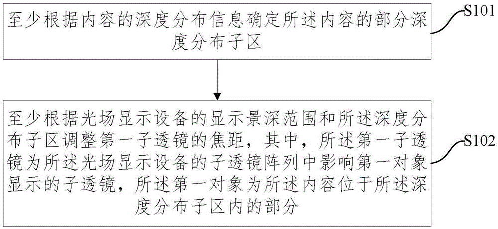
The embodiment of the invention discloses a light field display control method and device, and light field display equipment, wherein the light field display control method comprises the following steps of: determining a part of depth distribution sub-area of a content at least according to depth distribution information of the content; and adjusting the focal length of a first sub-lens at least according to the display field depth range of the light field display equipment and the depth distribution sub-area, wherein the first sub-lens is a sub-lens influencing display of a first object in a sub-lens array of the light field display equipment; and the first object is a part that the content is positioned in the depth distribution sub-area. By means of the light field display control method and device, and the light field display equipment disclosed by the invention, the display quality of the object in the local depth distribution sub-area in the to-be-displayed or displayed content can be improved.

Description

technical field [0001] The present application relates to the technical field of light field display, in particular to a light field display control method and device and a light field display device. Background technique [0002] Light field display technology was proposed as early as the beginning of the 20th century. Two representative implementations are: Lippmann's implementation based on Lenslet arrays in 1908 and Ives' implementation based on parallel gratings (Parallax Barriers) in 1903. In recent years, with the diversified demands of consumer electronics products for display devices, light field display technology has been applied to different scenarios and devices, such as: 3D displays, wearable devices, light field display devices for vision correction, etc. At present, the computing power and display resolution of electronic equipment and the gradual matching of hardware resource requirements of light field display technology provide good support for the popular...

Claims


Application Information

Patent Timeline
Patent Type & Authority Applications(China)
IPC IPC(8): H04N5/74H04N9/31H04N13/04H04N13/128
CPCH04N13/339H04N13/363H04N5/74H04N9/31H04N13/128H04N13/307H04N13/383H04N13/305H04N2013/0081
Inventor 周梁杜琳
Owner BEIJING ZHIGU RUI TUO TECH
Learn More