Easily mounted/dismounted limiting device for numerically-controlled bending machine

A limit device and bending machine technology, which is applied in the field of forging, can solve the problems of troublesome installation and disassembly of the rear limit device, high cost, time-consuming and laborious, etc., and achieve the goal of improving connection stability, increasing the scope of application, and improving the firmness of assembly Effect

Inactive Publication Date: 2017-02-08
黄石华强数控机床有限公司
View PDF0 Cites 0 Cited by
  • Summary
  • Abstract
  • Description
  • Claims
  • Application Information

AI Technical Summary

Problems solved by technology

[0003] The technical problem to be solved by the present invention is: in order to solve the problems existing in the above-mentioned background technology, an improved easy-to-load and disassemble limit device for CNC bending machines is provided, which solves the problem that the current workpiece placement is mainly done by manually adjusting the position of the workpiece. Adjusting and fixing is not only time-consuming and laborious, but also the instability of manual operation can easily affect the bending position and accuracy of the workpiece, and the rear side limit device currently used for bending machines is troublesome to install and disassemble, the cost is high, and the operation method is not good. Convenience question

Method used


Image

  • Easily mounted/dismounted limiting device for numerically-controlled bending machine
  • Easily mounted/dismounted limiting device for numerically-controlled bending machine

Examples


Embodiment Construction

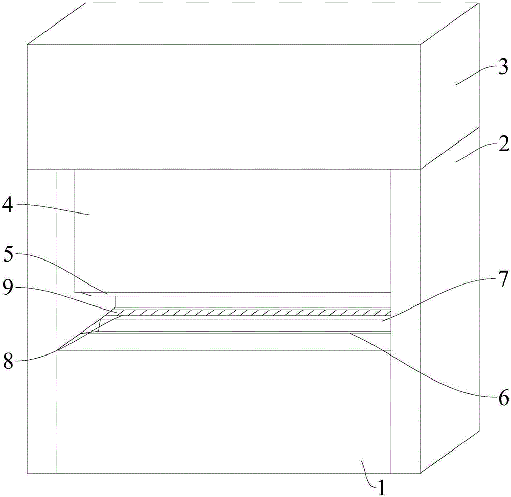
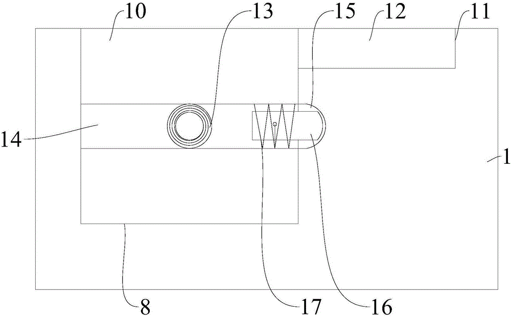
[0013] The present invention is described in further detail now in conjunction with accompanying drawing. These drawings are all simplified schematic diagrams, which only illustrate the basic structure of the present invention in a schematic manner, so they only show the configurations related to the present invention.

[0014] figure 1 and figure 2 The shown is an easy-to-load and disassemble limit device for a CNC bending machine, including a main frame 1, a main frame 2 and a hydraulic cylinder 3. The lower end of the hydraulic cylinder 3 is connected to a hydraulic slider 4, and the lower end of the hydraulic slider 4 is detachably connected. There is an upper mold 5 of the bending machine, and the upper surface of the main base 1 is provided with a fixed groove 6 corresponding to the position of the upper mold 5 of the bending machine. The fixed groove 6 is internally connected with a detachable lower mold 7 of the bending machine, and the upper surface of the main base...


PUM


Abstract

The invention relates to the technical field of forging technology, in particular to an easily mounted/dismounted limiting device for a numerically-controlled bending machine. The limiting device comprises a main base, a main frame and a hydraulic oil cylinder, wherein the lower end of the hydraulic oil cylinder is connected with a hydraulic sliding block; the lower end of the hydraulic sliding block is detachably connected with an upper die of the bending machine; and a fixing groove is formed in the upper surface of the main base and located at a position corresponding to the upper die of the bending machine. According to the easily mounted/dismounted limiting device for the numerically-controlled bending machine, an adjusting limiting groove, in which limiting blocks are arranged, is formed in the upper surface of the main base and located at a position near a lower die of the bending machine, and the positions and angles of limiting plates can be freely changed by changing the angles of the limiting blocks, so that the limiting plates can not only be placed in accommodating grooves to form a flat surface and but also be erected to form rear baffles and side baffles, thus greatly enlarging the application range of the limiting device; and by virtue of elastic pressing rods in the limiting blocks, the connection stability of the limiting blocks is greatly improved to improve the assembly firmness.

Description

technical field [0001] The invention relates to the technical field of forging, in particular to an easy-to-install and dismount limiting device for a numerically controlled bending machine. Background technique [0002] The CNC bending machine controls the up and down movement of the oil cylinder through the CNC system, thereby driving the mold installed on the slider to move up and down, and squeezes with the lower mold installed on the workbench to realize the bending of the workpiece. During the bending process, the position of the workpiece is mainly adjusted and fixed manually, which is not only time-consuming and laborious, but also the instability of manual operation can easily affect the bending position and accuracy of the workpiece, and it is currently used on the rear side of the bending machine The loading and unloading of the limit device is troublesome, the cost is high, and the operation method is also inconvenient. Contents of the invention [0003] The t...

Claims


Application Information

Patent Timeline
Patent Type & Authority Applications(China)
IPC IPC(8): B21D11/00B21D11/22
CPCB21D11/00B21D11/22
Inventor 李望安杨松祝波
Owner 黄石华强数控机床有限公司
Why Eureka
Try Eureka