Full Ceramic Gear Roll Mill

A gear roller and pulverizer technology, applied in the field of pulverized pulverizers, can solve the problem of no effective treatment method, etc.

Active Publication Date: 2019-05-07
宜兴精新粉体设备科技有限公司
View PDF10 Cites 0 Cited by
  • Summary
  • Abstract
  • Description
  • Claims
  • Application Information

AI Technical Summary

Problems solved by technology

This is a problem that needs to be solved urgently, but there has been no effective solution

Method used


Image

  • Full Ceramic Gear Roll Mill
  • Full Ceramic Gear Roll Mill

Examples


Embodiment 1

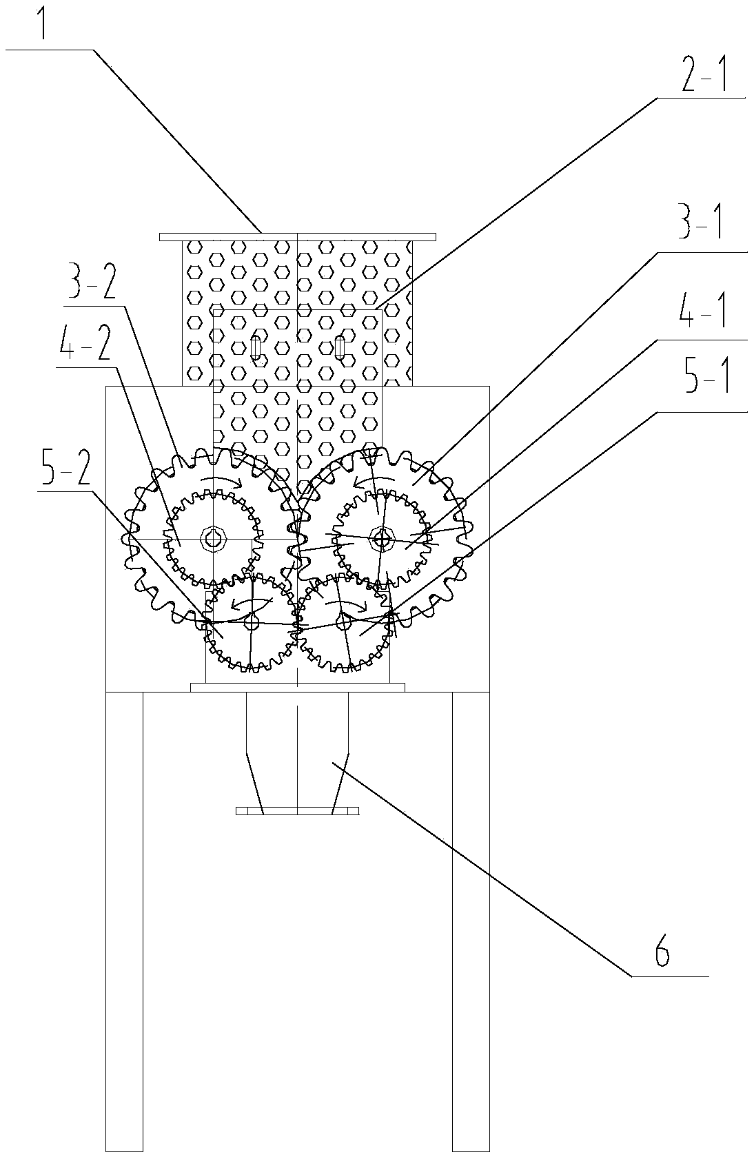
[0020] Embodiment 1: The all-ceramic gear roller pulverizer provided in this embodiment, the structural diagram is as follows figure 1 As shown, it includes a fuselage, a lower hopper 1 and a discharge port 6, the lower hopper 1 is located at the top of the fuselage, the discharge port is located at the bottom of the fuselage, a crushing chamber is provided in the fuselage, and the crushed A pair of oppositely rotating ceramic gear rollers are arranged above the discharge port 6 in the cavity, and the material falls into the gap between the two tooth surfaces of the pair of ceramic gear rollers and is crushed and crushed by the occlusal force of the two tooth surfaces.

[0021] The pair of ceramic gear rollers includes the first ceramic gear roller 3-1 and the second ceramic gear roller 3-2 driven by the pulverizing tooth roller transmission device. When there is no material filling, the pair of ceramic gear rollers are in a false meshing state. The pair of ceramic gear roller...

Embodiment 2

[0028] Embodiment 2: structure is basically the same as Embodiment 1, and the similarity is no longer repeated, and the difference is:

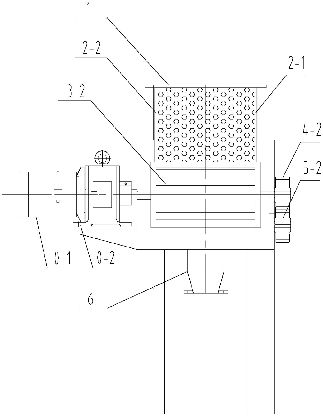
[0029] In Embodiment 2, only the first main shaft is drivingly connected to the motor among the first main shaft and the second main shaft. Specifically: if figure 2 As shown, one end of the first main shaft is driven and connected to the motor 0-1 through the reducer 0-2, while the first ceramic gear roller 3-1 is fixedly installed on the first main shaft, and the other end of the first main shaft is fixedly provided with the second A driving wheel 4-1.

[0030] Wherein, the first ceramic gear roller 3-1 and the second ceramic gear roller 3-2 are driven by the pulverizing gear roller transmission device to rotate inwardly.

[0031] At the same time, the inner wall of the feed port is equipped with ceramic lining or high wear-resistant organic matter. The fuselage includes a first arc-shaped shutter 2-1 and a first arc-shaped gate 2-1, wh...

Embodiment 3

[0034] Embodiment 3: structure is basically the same as Embodiment 1, and the similarity is no longer repeated, and the difference is:

[0035] The motor is a geared motor.

[0036] The fuselage includes a first arc-shaped shutter 2-1 and a first arc-shaped gate 2-1, which are oppositely arranged and located in the middle of the two ends of the first and second ceramic gear rollers, and are used to prevent materials from overflowing to both ends of the first and second ceramic gear rollers. The second arc flashboard 2-2. And the inner walls of the inlet and outlet are equipped with ceramic lining or high wear-resistant organic matter.

[0037] Meanwhile, in the third embodiment, the main shafts and skeletons of the first and second ceramic gear rollers are made of metal materials, and the material contact parts are made of ceramic materials or organic wear-resistant materials. The skeletons of the first and second spindles are made of metal materials, and the material contac...


PUM


Abstract

The invention discloses a full-ceramic gear-roller pulverizer which comprises a body, a feeding hopper and a discharging outlet. The feeding hopper is located at the top of the body; the discharging outlet is located at the bottom of the body; a pulverizing cavity is formed in the body; a pair of ceramic gear rollers rotating oppositely is arranged at the portions, above the discharging outlet, of the interior of the pulverizing cavity; and materials fall into the gap between the two tooth faces of the pair of ceramic gear rollers and are pulverized through grinding in a staggered-moving mode by means of the bite force of the two tooth faces. By adopting the pair of ceramic gear rollers rotating oppositely, small block-shaped materials fall into the rushing cavity from a feeding inlet, then fall into the gap between the two tooth faces of the pair of ceramic gear rollers rotating oppositely and are pulverized through grinding in a staggered-moving mode by means of the bite force of the two tooth faces, and therefore special pulverization of relevant high-technology materials is achieved.

Description

technical field [0001] The invention relates to a pulverizing device, in particular to a pulverizer for pulverizing. Background technique [0002] Today's high-tech materials are developing faster and faster, and there are more and more opportunities for innovation in processing equipment. In particular, ultra-pure materials in high-tech materials require that the deep processing equipment must be pollution-free. [0003] In the prior art, a vertical ceramic jaw-roller combination crusher provided by ZL2012202646823 and a roller crusher provided by ZL2012202646202 have good application effects, and hundreds of new ones are put into production every year. However, because the fineness of roller crushing can only reach 60 mesh, there is no machine type above 60 mesh, and from 100mm block to 60 mesh needs to be completed by the combination of jaw crusher and roller crusher, or the combination of two roller crushers, that is, two The combination of machines can be completed. ...

Claims


Application Information

Patent Timeline
Patent Type & Authority Patents(China)
IPC IPC(8): B02C4/08B02C4/42B02C4/30
CPCB02C4/08B02C4/30B02C4/42
Inventor 陆锁根
Owner 宜兴精新粉体设备科技有限公司
Why Eureka
Try Eureka