

Novel elevator counterweight frame
A technology of counterweight frame and elevator, which is applied to elevators in buildings, lifting equipment in mines, transportation and packaging, etc., can solve the problems of complex installation, high cost, high danger of high-altitude operation, and reduce the number of guide rail brackets. , the effect of ensuring worker safety
Pending Publication Date: 2017-02-15
马海英
View PDF0 Cites 0 Cited by
- Summary
- Abstract
- Description
- Claims
- Application Information
AI Technical Summary
Problems solved by technology
[0008] The technical problem solved by this patent: In order to fundamentally solve the complicated installation, high cost and high risk of high-altitude operation of existing products, a new elevator counterweight frame is proposed
Method used
View moreImage
Smart ImageViewing Examples

Examples
Embodiment Construction
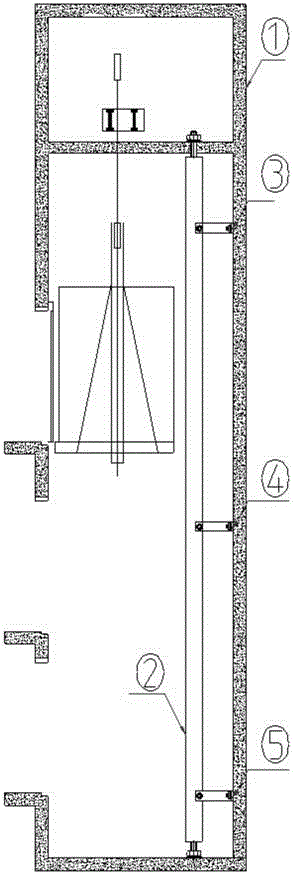
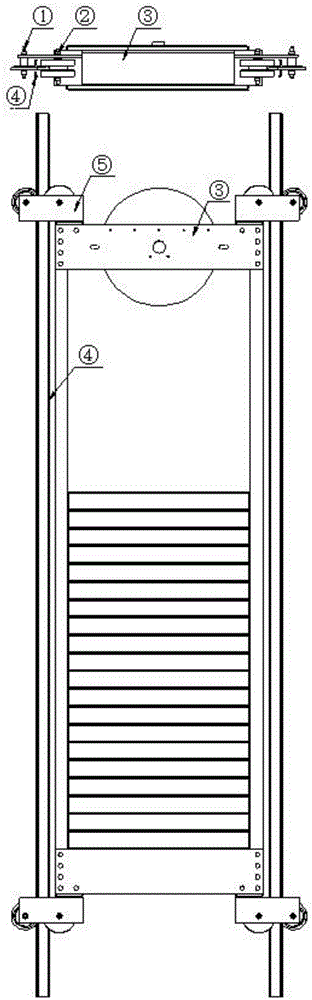
[0018] 1. New counterweight guide frame device: one roller is set on the elevator counterweight frame to roll along the guide rail, and the other is limited to the back of the guide rail and moves with the counterweight; the upper and lower ends of the elevator counterweight guide rail and the guide rail connecting plate in the middle of the hoistway are used The bracket is fixed on the well wall, and the guide rails in other positions are not fixed with brackets.
Login to View More PUM
 Abstract
The invention provides a novel elevator counterweight frame and belongs to the technical field of elevator counterweight frames. The defects that existing products are complex in installation, long in construction period, high in cost and high in risk of high altitude operation are fundamentally overcome. According to the technical scheme of the brand-new elevator counterweight frame, rollers are arranged on the elevator counterweight frame, are limited to the back face of a guide rail, and move along with counterweights; and the upper end and the lower end of the elevator counterweight guide rail and a guide rail connecting plate in the middle of a shaft are fixed to the wall of the shaft through brackets, and no bracket for fixing is arranged at other positions of the counterweight guide rail.
Description
technical field [0001] This patent relates to an elevator counterweight frame. Background technique [0002] The situation of the existing elevator counterweight frame is: [0003] 1. When installing the elevator, each section of the counterweight rail needs to be fixed with multiple brackets. [0004] Its flaws: [0005] 1. To install multiple brackets, a large number of holes need to be drilled in the hoistway. The workload is heavy, the consumables are high, the cost is high, and the efficiency is low. [0006] 2. Accidental derailment accidents are prone to occur. [0007] 3. The construction is difficult, the safety is low, and the risk is high. Contents of the invention [0008] The technical problem solved by this patent: In order to fundamentally solve the complicated installation, high cost and high risk of high-altitude operation of existing products, a brand-new elevator counterweight frame is proposed. [0009] The technical solution adopted by the present...
Claims
Login to View More Application Information
Patent Timeline
 IPC IPC(8): B66B11/00B66B17/12
Inventor马海英
Owner马海英