
Hollow plate beam structure for ultrahigh performance concrete hinge joint connection

A hollow slab girder, ultra-high performance technology, applied in bridges, bridge parts, bridge materials, etc., can solve the problems of loss of hollow slab girder structure, affecting durability and safety, fragile concrete, etc., to improve the horizontal connection. performance, improved durability and safety, improved strength effects

Inactive Publication Date: 2017-02-15
SHANGHAI URBAN CONSTR DESIGN RES INST GRP CO LTD
View PDF7 Cites 6 Cited by
  • Summary
  • Abstract
  • Description
  • Claims
  • Application Information

AI Technical Summary

Problems solved by technology

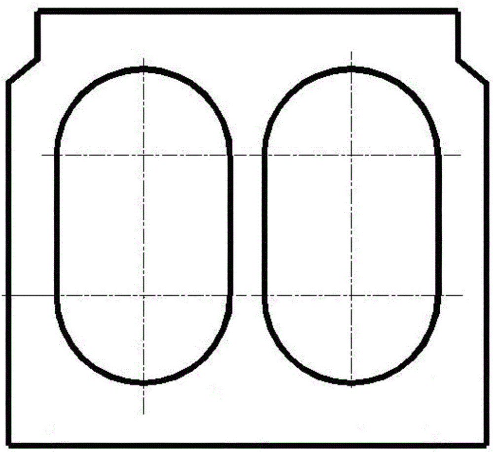
[0002] Existing hollow slab girders (such as figure 1 As shown) due to the weak reinforcement of the hinge joint, the concrete in the hinge joint is easily broken, which greatly affects its durability and safety. In recent years, it has been gradually eliminated in bridges on important roads
At present, the industry has changed it to rigidly connected hollow slab girders, but the construction process of rigidly connected hollow slab girders is complicated, and formwork needs to be erected, which makes the hollow slab girder structure lose its original convenience and speed.

Method used


Image

  • Hollow plate beam structure for ultrahigh performance concrete hinge joint connection
  • Hollow plate beam structure for ultrahigh performance concrete hinge joint connection
  • Hollow plate beam structure for ultrahigh performance concrete hinge joint connection

Examples


Embodiment Construction

[0025] In order to make the purpose, technical solutions and advantages of the embodiments of the present invention more clear, the technical solutions in the embodiments of the present invention will be clearly and completely described below in conjunction with the drawings in the embodiments of the present invention. Based on the embodiments of the present invention, all other embodiments obtained by persons of ordinary skill in the art without creative efforts fall within the protection scope of the present invention.

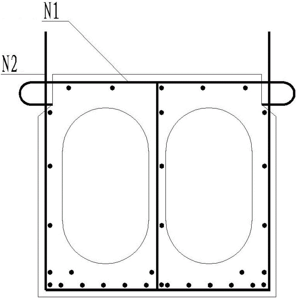
[0026] Such as Figure 1 to Figure 6 As shown, a hollow slab beam structure of ultra-high-performance concrete hinged joints, including hollow slab beams, the sides of several hollow slab beams are connected by steel bars to form a hinged joint structure, and concrete N4 is filled in the hinged joint structure.

[0027] Wherein, several groups of steel bars are arranged in the hollow slab beam along the length direction, and each group of steel bars includes...


PUM


Abstract

The invention provides a hollow plate beam structure for ultrahigh performance concrete hinge joint connection. The hollow plate beam structure comprises a hollow plate beam. A plurality of hollow plate beam side faces are connected though steel bars to form a hinge joint structure which is filled with ultrahigh performance concrete; the two sides of the part, close to the upper end, of the hollow plate beam are concave inward; the upper end of the hollow plate beam is provided with horizontally stretching steel bars stretching out from the two inward-concave sides; the two ends, stretching out of the two sides of the hollow plate beam, of each horizontally stretching steel bar are bent to form hooks; the positions, close to the two sides, of the hollow plate beam are provided with perpendicularly stretching steel bars which upward stretch out of the hollow plate beam; a semicircular circle is defined by each perpendicularly stretching steel bar and the corresponding hook; the circles of every two adjacent hollow plate beam side faces are overlapped; longitudinally penetrating steel bars penetrate into the overlapped circles; the horizontally stretching steel bars, the perpendicularly stretching steel bars and the longitudinally penetrating steel bars are fixed as a whole. According to the hollow plate beam structure, the hinge joint hook steel bars and the longitudinally penetrating steel bars are additionally arranged, and a hinge joint is filled with ultrahigh performance concrete, so that the transverse connection performance, the durability and the safety are largely improved.

Description

technical field [0001] The invention relates to the technical field of hollow slab beams, in particular to a hollow slab beam structure connected by hinge joints of ultra-high performance concrete. Background technique [0002] Existing hollow slab girders (such as figure 1 As shown) due to the weak reinforcement of the hinge joint, the concrete in the hinge joint is easily broken, which greatly affects its durability and safety. In recent years, it has gradually begun to be eliminated in bridges on important roads. At present, the industry has changed it to a rigidly connected hollow slab girder, but the construction process of the rigidly connected hollow slab girder is complicated, and formwork needs to be erected, which makes the hollow slab girder structure lose its original convenience and speed. [0003] Therefore, there is an urgent need for a hollow slab girder with high durability and safety to overcome the deficiencies in the prior art. Contents of the inventio...

Claims


Application Information

Patent Timeline
IPC IPC(8): E01D2/04E01D19/00E01D101/26
CPCE01D2/04E01D19/00E01D2101/26
Inventor 郭卓明
Owner SHANGHAI URBAN CONSTR DESIGN RES INST GRP CO LTD
Learn More