Eureka AIR delivers breakthrough ideas for toughest innovation challenges, trusted by R&D personnel around the world.

A foundation pit support system and its construction method

A technology of foundation pit support and construction method, which is applied in basic structure engineering, excavation, construction, etc., can solve the problems of inability to guarantee the control of small deformation, narrow space, and inability to carry out effective support measures for subway structures.

Active Publication Date: 2019-02-19
BEIJING URBAN CONSTR EXPLORATION & SURVEYING DESIGN RES INST
View PDF5 Cites 0 Cited by
  • Summary
  • Abstract
  • Description
  • Claims
  • Application Information

AI Technical Summary

Problems solved by technology

[0006] In large cities with underground rail transit, the support construction of building foundation pits should also fully consider the safety of underground traffic. When designing and constructing foundation pits for foundation works near subway structures, a series of problems and difficulties are often encountered, such as narrow space, inability to carry out effective support measures around subway structures, and inability to ensure control of small deformations; for example: for The proposed structural system is 6m-12m away from the existing subway track structure, and the building foundation pit is deeper than the subway track structure, and based on the geological environment of the foundation pit, the main strata are silt layer, clay layer and sandy soil layer, and are affected by the second layer Due to the impact of groundwater diving, based on complex engineering geological conditions and surrounding environments, conventional foundation pit support methods can no longer meet the needs of safety and feasibility

Method used


Image

  • A foundation pit support system and its construction method
  • A foundation pit support system and its construction method
  • A foundation pit support system and its construction method

Examples


Embodiment Construction

[0082] The present invention will be described in further detail below in conjunction with the accompanying drawings and examples, but the embodiments of the present invention are not limited to the scope indicated by the examples.

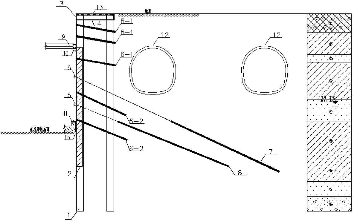
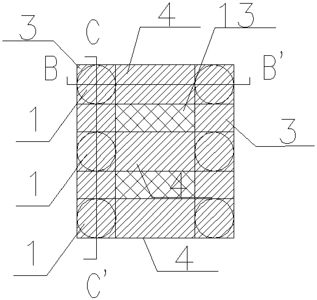
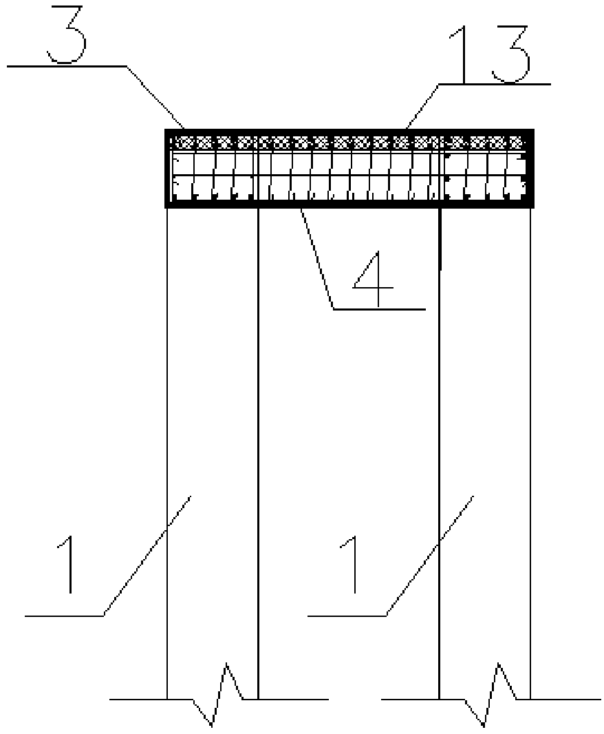
[0083] see attached Figures 1 to 9 As shown, a foundation pit support system and its construction method, wherein:

[0084] A foundation pit support system, comprising: a retaining pile system and a groundwater control subsystem;

[0085] Further, the enclosure pile system includes: enclosure pile 1, a fertilizer groove 15 is opened between the enclosure pile 1 and the basement wall, and the enclosure pile 1 is also connected with a crown beam 3, a connecting The beam 4 and the waist beam 5, the protective structure between the piles, the grouting flower tubes 6-1 and 6-2, the prestressed anchor rods 7 and 8, and the steel support 9 structure are arranged between the surrounding protection piles 1. The crown beam 3 is arranged on the top of the...


PUM


Abstract

The invention discloses a foundation pit support system and a construction method of the foundation pit support system. The foundation pit support system comprises a fender pile subsystem and an underground water control subsystem. The fender pile subsystem comprises fender piles. A wide groove is formed between the fender piles and a basement exterior wall. The fender piles are further connected with crown beams, connection beams, waist beams and steel enclosing purlins. An inter-pile soil protective structure, a grouting pipe, a pre-stressed anchor and a steel supporting structure are arranged between every two adjacent fender piles. The tops of the fender piles are provided with the crown beams, the waist beams are fixed to the middles of the fender piles, and the connection beams are arranged between the front and rear rows of the crown beams. The underground water control subsystem comprises a waterproof curtain. The problem of potential safety hazards caused when foundation pit construction is carried out on foundation engineering near an underground railway track can be eliminated, deformation caused by foundation pit excavation on surrounding soil and structures is reduced to the largest degree, construction of the support system is more efficient, and the foundation pit support system is higher in strength and higher in safety.

Description

technical field [0001] The invention relates to the technical field of foundation engineering protection in building construction, in particular to a foundation pit support system and a construction method thereof. Background technique [0002] The building foundation pit refers to the space below the ground excavated for the construction of the building foundation and the basement. After the excavation, multiple free surfaces are formed around the building foundation pit to form the foundation pit enclosure. We surround the foundation pit One side of the body is called the side wall of the foundation pit; [0003] The excavation of the building foundation pit will inevitably have a certain impact on the surrounding environment. In order to ensure the safety of the underground construction structure and the surrounding environment of the foundation pit, the support, reinforcement and protection measures adopted for the side wall of the foundation pit and the surrounding envi...

Claims


Application Information

Patent Timeline
Patent Type & Authority Patents(China)
IPC IPC(8): E02D17/04E02D19/18
CPCE02D17/04E02D19/18
Inventor 董慧超刘志强韩泽坤冯科明
Owner BEIJING URBAN CONSTR EXPLORATION & SURVEYING DESIGN RES INST
Why Eureka
Eureka Blog
Learn More