Self-closing liquid level observer with adjustable center distance

A center-to-center, self-closing technology, used in liquid level indicators, liquid/fluid solids measurement, instruments, etc., can solve the problems of leakage of liquid level observers, inconvenient center distance adjustment, and inconvenient installation, so as to reduce leakage The effect of danger, cost saving and easy installation

Active Publication Date: 2018-07-17
TIANJIN HANGLIAN TIKE SCI & TECHN
View PDF14 Cites 0 Cited by
  • Summary
  • Abstract
  • Description
  • Claims
  • Application Information

AI Technical Summary

Problems solved by technology

The center distance of the liquid level observers currently on the market cannot be adjusted. The biggest disadvantage of the inability to adjust the center distance is that it is inconvenient to install.
The installation procedure of the liquid level observer is usually to first punch the upper and lower holes 100a, 100b on the liquid storage tank 10 according to the center distance, and then weld the union 101 to the holes 100a, 100b opened by the liquid storage tank 10, so that there is It may cause center distance deviation, that is, the distance between the centers of the two holes 100a, 100b on the liquid storage tank 10 deviates from the center distance L of the liquid level observer. If the deviation from the center distance L is too large, it may cause liquid level observation. device leak
Because there is a gasket between the valve body assembly 103 and the sheath pipe assembly 104 of the liquid level observer, they cannot be moved after assembly. leakage
To solve this problem, we can make a welding tool, but the height of the box is different from the center distance, and the cost will increase if the tooling is used.

Method used


Image

  • Self-closing liquid level observer with adjustable center distance
  • Self-closing liquid level observer with adjustable center distance
  • Self-closing liquid level observer with adjustable center distance

Examples


Embodiment Construction

[0017] Hereinafter, the present invention will be further described in detail through the drawings and specific embodiments.

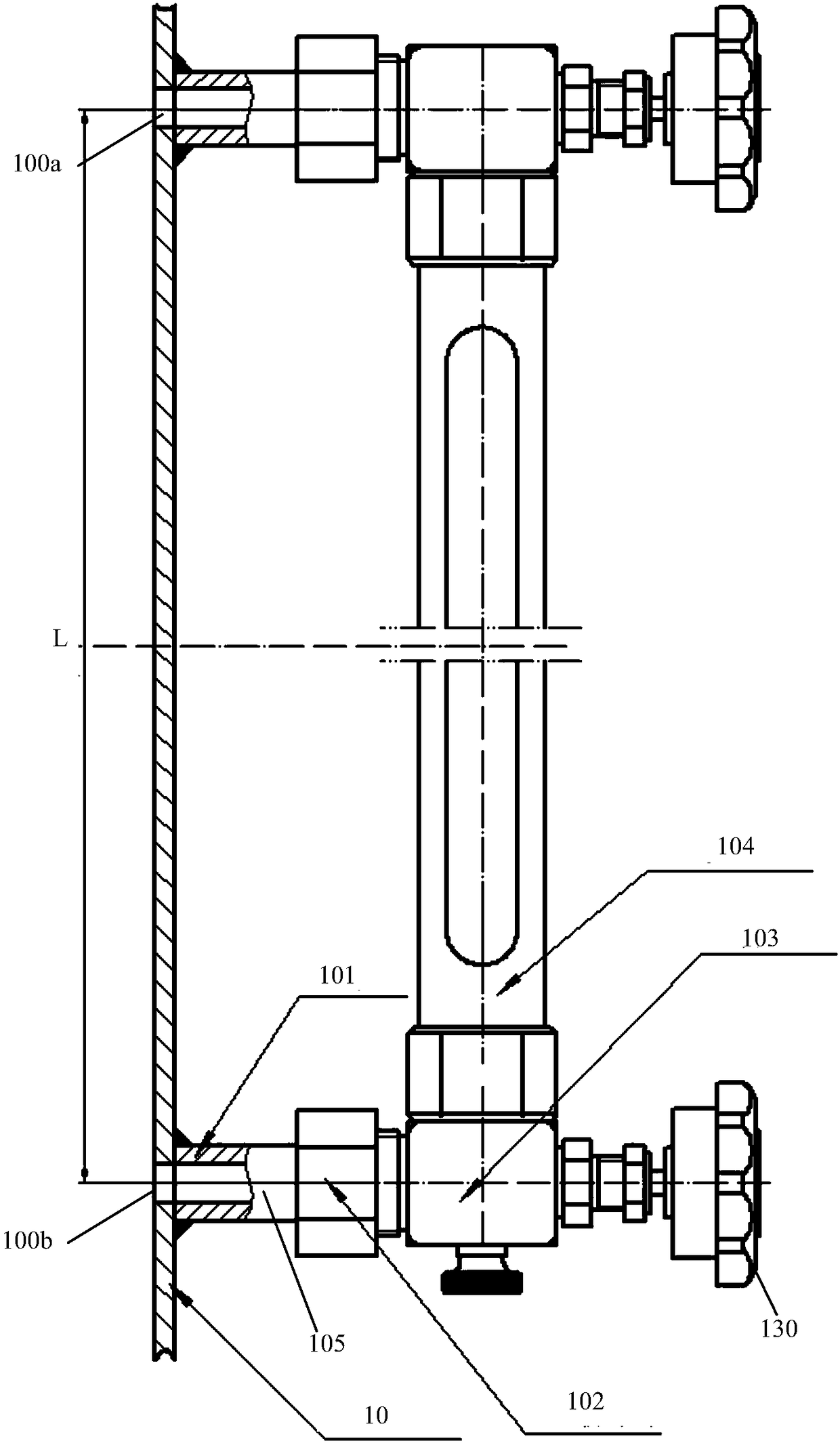
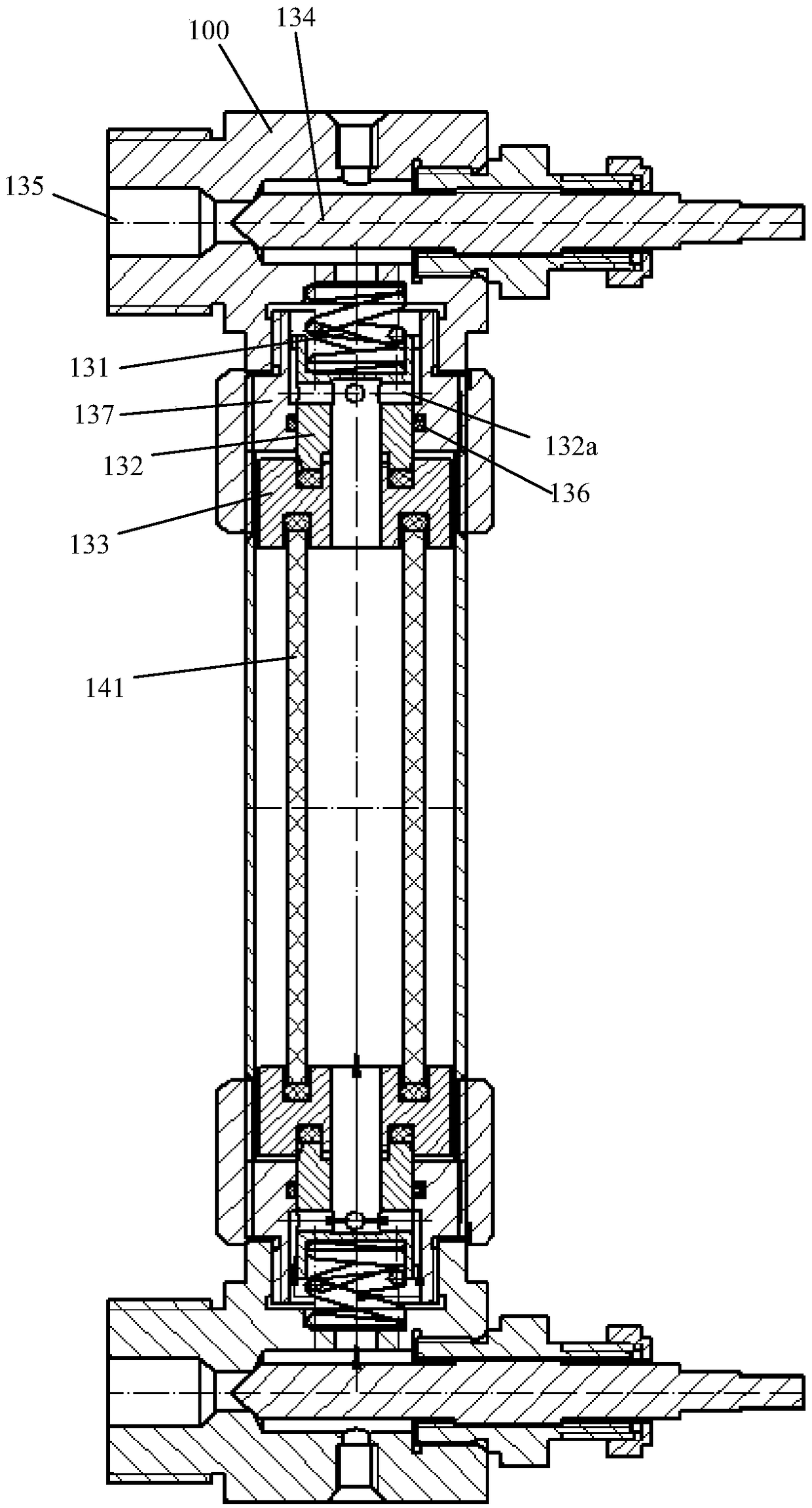
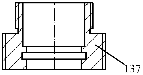
[0018] As shown in the figure, this embodiment provides a self-closing liquid level observer with adjustable center distance, which includes two upper and lower valve body assemblies 103 and a jacket tube assembly 104 in the middle; the valve body assembly 103 includes a valve Body 100, the main valve core 134 located in the valve body 100, the self-closing valve core 132, the self-closing valve sleeve 137, the spring 131 and the compression sleeve 133, the self-closing valve core 132 is located in the self-closing valve sleeve 137 and Can move within the self-closing valve sleeve 137; among the two sets of valve body assemblies 103, the self-closing valve sleeves 137 of at least one set of valve body assemblies 103 are screwed to the valve body 100, the The side of the self-closing valve sleeve 137 close to the valve body 100 is provided with an internal...


PUM


Abstract

The invention discloses a self-closing liquid level observer capable of regulating a center distance. The self-closing liquid level observer comprises two groups of valve assemblies located at upper and lower parts and a protective sleeve assembly located in the middle; each valve assembly comprises a valve body as well as a main valve element, a self-closing valve element, a self-closing valve sleeve, a spring and a pressing sleeve which are located in the valve body, and the self-closing valve element is located in the self-closing valve sleeve and can move in the self-closing valve sleeve; the self-closing valve sleeve of at least one group of valve assembly in the two groups of valve assemblies is in threaded connection to the valve body; an internal thread is arranged at the side, close to the corresponding valve body, of each self-closing valve sleeve and is in threaded connection with a plug in which a liquid through hole is formed; one end of each spring abuts against the corresponding plug, and the other end of each spring abuts against the self-closing valve element; and the end, far away from the corresponding spring, of each self-closing valve element abuts against the pressing sleeve. The problem of mounting deviation of the center distance is solved, so that the liquid level observer is more conveniently mounted; and more importantly, the leakage problem caused after a period of time since the liquid level observer is mounted is solved.

Description

Technical field [0001] The invention relates to a liquid level observer, in particular to a self-closing liquid level observer with adjustable center distance. Background technique [0002] The self-closing liquid level observer is an instrument installed on the liquid storage tank 10 to observe the liquid level, such as figure 1 As shown, the self-closing liquid level observer usually includes two sets of upper and lower unions 101, a liquid outlet pipe 105, a union nut 102, a valve body assembly 103, and a sheathing tube assembly 104 in the middle. In the valve body assembly 103, one end of the spring 131 is pressed against the valve body 100, and the other end is pressed against the self-closing valve core 132; the self-closing valve core 132 is pressed against the compression sleeve 133; between the two compression sleeves 133 is a sheath In the glass tube 141 of the tube assembly 104, the self-closing valve core 132 is located inside the self-closing valve sleeve 137. Rotat...

Claims


Application Information

Patent Timeline
Patent Type & Authority Patents(China)
IPC IPC(8): F16K21/04G01F23/00
CPCF16K21/04G01F23/00
Inventor 谢炳玉吴建君
Owner TIANJIN HANGLIAN TIKE SCI & TECHN
Why Eureka
Try Eureka