
A lvdt sensor installation structure for an actuator

An installation structure and sensor technology, applied in the direction of using electrical devices, instruments, measuring devices, etc., can solve problems such as low reliability, jumping electromechanical actuators, external media interference, etc., to improve accuracy and reliability, and improve installation Strength, the effect of realizing redundancy configuration

Active Publication Date: 2020-07-14
BEIJING RES INST OF PRECISE MECHATRONICS CONTROLS +1
View PDF7 Cites 0 Cited by
  • Summary
  • Abstract
  • Description
  • Claims
  • Application Information

AI Technical Summary

Problems solved by technology

[0002] Existing electromechanical actuators often use potentiometers as their linear displacement measurement methods, while the linear displacement sensor of the positioner is a contact sensor, which has the problems of severe wear and reduced measurement accuracy after long-term work. The signal jumps and then causes the vibration of the electromechanical actuator, and the contact end of the potentiometer is polluted by grease, which reduces the measurement accuracy
[0003] At present, the existing LVDT sensors for actuators often do not take insulation measures. The LVDT sensors are prone to receive electromagnetic interference from other components, which affects the test accuracy. In order to reduce the electromagnetic interference of the LVDT sensor from the actuator motor or other components, it is necessary to LVDT sensor is insulated
[0004] Some actuators adopt the external structure of LVDT sensor, which has low reliability and is easily disturbed by external media.

Method used


Image

  • A lvdt sensor installation structure for an actuator
  • A lvdt sensor installation structure for an actuator
  • A lvdt sensor installation structure for an actuator

Examples


Embodiment Construction

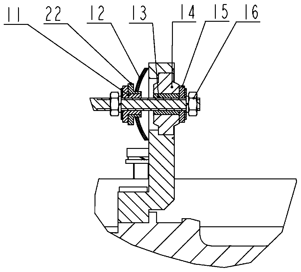
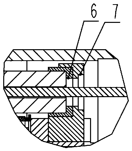
[0032] The LVDT sensor is a differential transformer displacement sensor, such as figure 1 with Figure 5 As shown, two sets of LVDT sensor installation structures for an actuator according to the present invention are installed side by side inside the actuator. The iron core connecting rod 3 of the LVDT sensor is fixedly connected with the ball screw nut 18 of the actuator, which can directly measure the linear output position of the actuator; interference problem.

[0033] A LVDT sensor installation structure for an actuator of the present invention includes a first connection assembly, a second connection assembly, a flexible structure assembly, a support assembly, an iron core connecting rod 3, and an insulation assembly;

[0034] The outlet end of the LVDT sensor stator 1 is fixed on the reducer housing 20 of the actuator through the first connection assembly, the outlet end is the first end of the LVDT sensor stator 1, and the other end is the second end; the LVDT sens...


PUM


Abstract

The invention provides an LVDT sensor mounting structure for an actuator. The LVDT sensor mounting structure comprises a first connection assembly, a second connection assembly, a flexible structure assembly and an iron core connecting rod. The wire outlet end of an LVDT sensor stator is fixed to a speed reducer case of the actuator through the first connection assembly, the wire outlet end is used as the first end of the LVDT sensor stator, and the other end is used as the second end of the LVDT sensor stator; the second end of the LVDT sensor stator is fixed to an actuator case through the second connection assembly; the first end of the iron core connecting rod is fixed to a ball screw nut of the actuator through the flexible structure assembly; the second end of the iron core connecting rod is connected with an LVDT sensor iron core; the axis of the iron core connecting rod is coaxial with the axis of the LVDT sensor iron core. According to the LVDT sensor mounting structure, an LVDT sensor is used for measuring the line displacement of the electromechanical actuator, and the LVDT sensor is a non-contacting sensor, so that the problem that a contact sensor is easy to wear is avoided, and the service life of the sensor is prolonged; meanwhile, the LVDT sensor has relatively high measurement precision.

Description

technical field [0001] The invention relates to an actuator LVDT sensor installation structure, which belongs to the technical field of electromechanical servo electromechanical actuators. Background technique [0002] Existing electromechanical actuators often use potentiometers as their linear displacement measurement methods, while the linear displacement sensor of the positioner is a contact sensor, which has the problems of severe wear and reduced measurement accuracy after long-term work. Signal jumping causes the vibration of the electromechanical actuator, and the contact end of the potentiometer is polluted by grease, which reduces the measurement accuracy. [0003] At present, the existing LVDT sensors for actuators often do not take insulation measures. The LVDT sensors are prone to receive electromagnetic interference from other components, which affects the test accuracy. In order to reduce the electromagnetic interference of the LVDT sensor from the actuator mo...

Claims


Application Information

Patent Timeline
Patent Type & Authority Patents(China)
IPC IPC(8): G01B7/02
CPCG01B7/02
Inventor 刘伟崔佩娟肖翀林晨侯占林
Owner BEIJING RES INST OF PRECISE MECHATRONICS CONTROLS
Learn More