Modular frame down lamp

A downlight and frame technology, which is applied to the parts of lighting devices, semiconductor devices of light-emitting elements, lighting and heating equipment, etc., can solve problems such as rotten edges or stains of ceiling installation holes, safety accidents, and inability to replace the light source part alone. , to achieve the effect of reducing procurement costs and construction costs

Active Publication Date: 2017-02-15
江苏靖隆合金钢机械制造有限公司
View PDF8 Cites 7 Cited by
  • Summary
  • Abstract
  • Description
  • Claims
  • Application Information

AI Technical Summary

Problems solved by technology

[0002] The LED downlights in the prior art are installed on the ceiling through a retaining spring structure. As the use time increases, the brightness of the LED downlights will gradually decrease, especially in shopping malls, hospitals, hotels and other occasions with long-term lighting. The LED downlight needs to be replaced every year. On the one hand, when replacing the LED downlight, the entire LED downlight needs to be replaced, and the light source part cannot be replaced separately, resulting in a waste of resources. When installing the lamp, it is necessary to pull or pry the edge of the lamp forcibly, which will cause bad edges or stains around the ceiling installation hole, which will seriously affect the aesthetics of the ceiling, and even cause the need to repair the roof twice
[0003] In addition, when replacing LED downlights, the old downlight line needs to be cut off, and the new downlight also needs to be rewired. Since there are many and hidden wires in the roof, professional personnel are required to replace the lamps, and wire connections are often wrong or connected. Inadequate wrapping of parts may cause safety accidents, and the reliability is not high

Method used


Image

  • Modular frame down lamp
  • Modular frame down lamp
  • Modular frame down lamp

Examples


Embodiment Construction

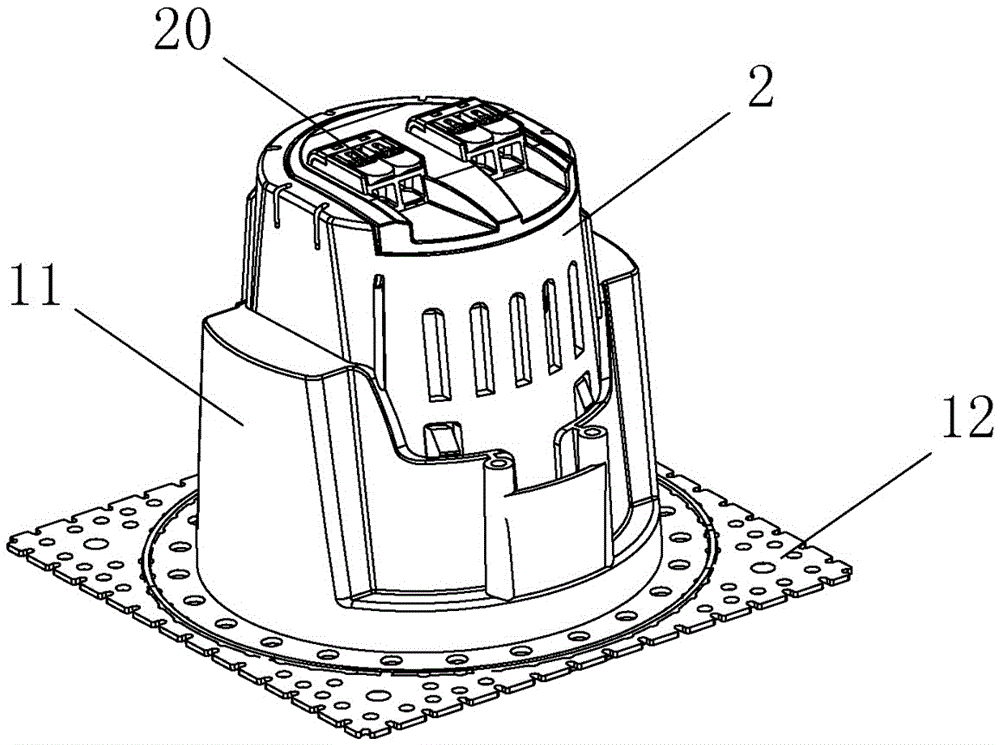
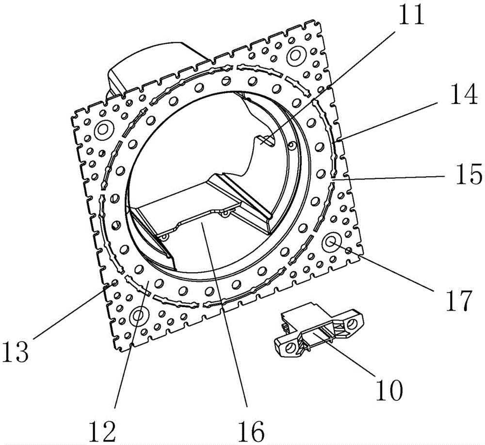
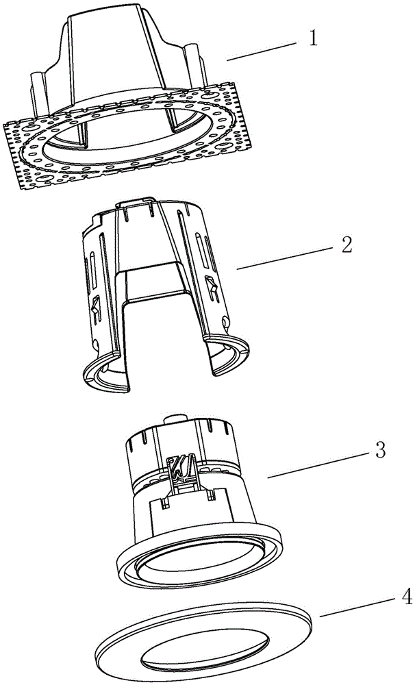
[0025] refer to Figure 1 to Figure 7 , a modular downlight with a frame, which is composed of four parts: an embedded part 1, an intermediate part 2, a lamp body 3 and a cover 4; the intermediate part 2 is installed in the embedded part 1; the The lamp body 3 is installed in the middle part 2, and a connecting structure is provided between the lamp body 3 and the middle part 2 or the embedded part 1; the surface cover 4 is movably connected to the middle part 2 or the lamp body 3 at the lower end.

[0026] In this embodiment, the fastening structure includes a clamping seat 10 provided on the embedded part 1 and a clamping joint 30 provided on the lamp body 3, and the inner wall of the embedded part 1 is provided with A cavity 16 with an opening downward, the clamping seat 10 is fixed in the cavity 16 by screws. The clamping joint 30 and the clamping seat 10 form a rebound self-locking structure. The rebound self-locking structure is also called a rebound self-locking devi...


PUM


Abstract

The invention discloses a modular frame down lamp. The modular frame down lamp is composed of an embedded part, an intermediate part, a lamp body and a face cover, wherein the intermediate part is mounted in the embedded part; the lamp body is mounted in the intermediate part, and a fixed connecting structure is arranged between the lamp body and the intermediate part or between the lamp body and the embedded part; and the face cover is movably connected to the lower end of the intermediate part or the lower end of the lamp body, the embedded part is fixed to a ceiling in advance during decoration, the intermediate part is clamped in the embedded part after wiring, then the lamp body is mounted in the intermediate part, and finally the face cover is mounted on the lamp body. After lamplight of the down lamp becomes dim or the down lamp is damaged, a user can replace the lamp body or the face cover by himself / herself extremely conveniently since re-wiring is not needed, the embedded part and the intermediate part which are mounted on the ceiling do not needed to be replaced, and edge breakage or stains around a mounting hole are avoided; and compared with a whole lamp replacing way in the prior art, the purchasing cost and construction cost for lamp replacement can be reduced for the user.

Description

technical field [0001] The invention relates to a lighting fixture, in particular to an LED downlight. Background technique [0002] The LED downlights in the prior art are installed on the ceiling through a retaining spring structure. As the use time increases, the brightness of the LED downlights will gradually decrease, especially in shopping malls, hospitals, hotels and other occasions with long-term lighting. The LED downlight needs to be replaced every year. On the one hand, when replacing the LED downlight, the entire LED downlight needs to be replaced, and the light source part cannot be replaced separately, resulting in a waste of resources. When installing the lamp, it is necessary to forcefully pull or pry the edge of the lamp, which will cause rotten edges or stains around the ceiling installation hole, which will seriously affect the aesthetics of the ceiling, and even cause the need to repair the roof twice. [0003] In addition, when replacing LED downlights,...

Claims


Application Information

Patent Timeline
Patent Type & Authority Applications(China)
IPC IPC(8): F21S8/02F21V17/16F21V17/12F21V19/00F21V23/06F21Y115/10
CPCF21S8/026F21V17/12F21V17/164F21V19/0025F21V23/06
Inventor 吴红梅
Owner 江苏靖隆合金钢机械制造有限公司
Why Eureka
Try Eureka