
Surgical instrument comprising bearing

A surgical tool and tool technology, applied in the field of surgical tools, can solve the problems of time-consuming and cost-consuming tool users, and the inability to use the shell or handpiece as expected, so as to achieve high availability and reliability, save cost and/or time , the effect of reducing failure

Pending Publication Date: 2021-03-16
AESCULAP AG
View PDF1 Cites 0 Cited by
  • Summary
  • Abstract
  • Description
  • Claims
  • Application Information

AI Technical Summary

Problems solved by technology

During repair or replacement, the housing or handpiece cannot be used as intended, thus costing the user of the tool time and cost

Method used


Image

  • Surgical instrument comprising bearing
  • Surgical instrument comprising bearing
  • Surgical instrument comprising bearing

Examples


Embodiment Construction

[0037] Embodiments of the present disclosure will be described below based on the drawings.

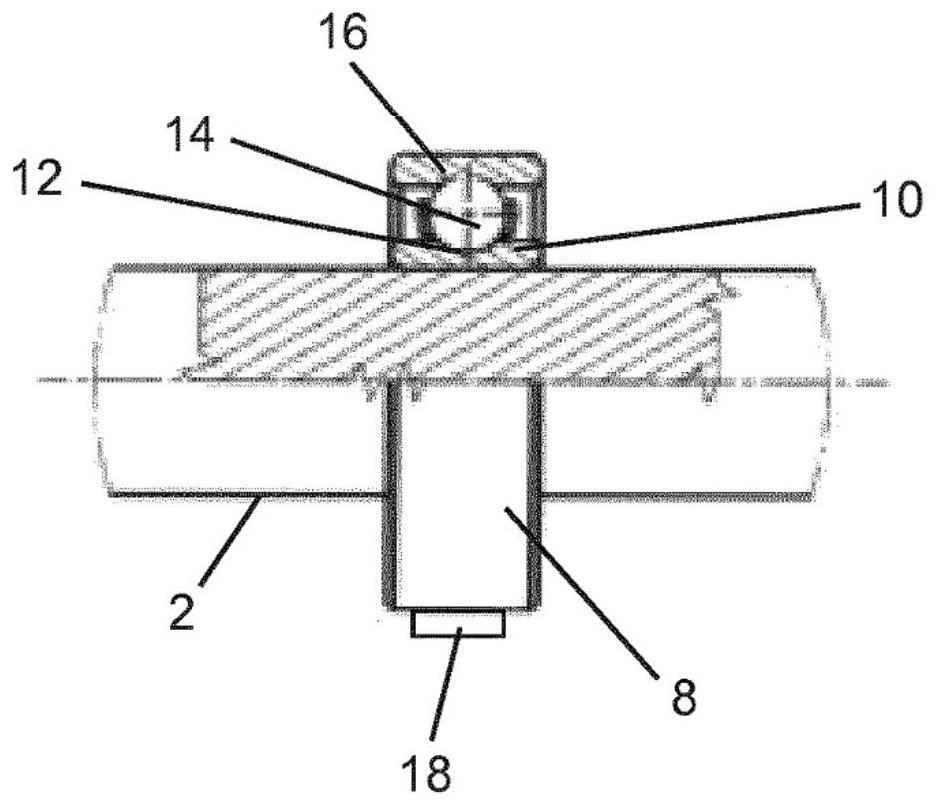
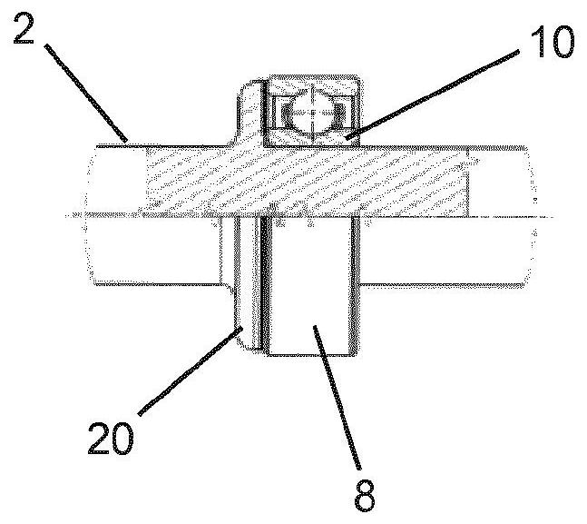
[0038] Figure 1A A surgical milling tool 1 is shown with a tool shaft 2 having a main section 3 , an actuator 4 on the distal end section and a coupling structure 6 on the proximal end section. The actuator 4 is embodied here as a milling cutter, but it could also be a drilling machine. The tool shaft 2 is tapered towards its distal end section. The radial dimension of the coupling structure 6 is narrower than that of the tool shank 2 for easy insertion into a housing or handpiece (not shown). A drive (not shown) is provided in the housing, with which the tool 1 can be coupled via the coupling structure 6 in such a way that the tool takes over the rotational movement caused by the drive. In the case of rotation of the tool 1, a bearing mechanism between the tool 1 and the housing is required. According to the invention, therefore, a pivot bearing 8 is provided on the tool shaft 2 ...


PUM


Abstract

Provided is a surgical instrument (1), in particular a surgical milling or drilling instrument, comprising an instrument shank (2) having an effector (4) at its distal end portion and a coupling structure (6) at its proximal end portion. The coupling structure is designed to be selectively coupled, is axially fixedly and for conjoint rotation, to a drive received in a housing, preferably a handpiece, in order to thereby transmit a rotation of the drive to the instrument shank (2), so that at least one rotary bearing (8) for rotatably supporting the instrument shank (2) on the housing, preferably handpiece, is located between the instrument shank (2) and the housing, preferably handpiece. The rotary bearing (8) and the instrument shank (2) are combined in a unit which, for coupling to the drive can be introduced into the housing, and for uncoupling from the drive can be withdrawn from the housing, as a single unit.

Description

technical field [0001] The invention relates to a surgical tool with a support structure. Background technique [0002] Several surgical tools are known from the prior art, for example surgical milling tools or drilling tools, which have a tool shaft comprising a proximal and a distal end section which is a working end with an actuator. The tool can be coupled by means of its proximal end section in a rotationally fixed and axially fixed manner to the drive in the housing via a coupling structure in order to transmit the rotational movement of the drive to the tool, which then surrounds the Its longitudinal axis rotates. For the necessary support of the tool relative to the housing, this housing has a pivot bearing firmly integrated in it. The tools are usually exchangeably connected to the housing so that the housing can be used multiple times and equipped with different or different types of tools. [0003] Such a tool is known, for example, from document US RE 29 736, ...

Claims


Application Information

Patent Timeline
Patent Type & Authority Applications(China)
IPC IPC(8): A61B17/16
CPCA61B17/1631B23C5/1009B23C2260/08B23B31/005B23B2260/008A61B17/162
Inventor 罗兰-阿洛伊斯·霍格尔拉尔夫·菲斯特安德烈·比尔克
Owner AESCULAP AG
Learn More