
Base structure of indoor unit of air conditioner

A technology for indoor units and indoor units of air conditioners, which are applied in air conditioning systems, space heating and ventilation, heating methods, etc., can solve the problems of poor air conditioning comfort, easy accumulation of dust, and influence on the comfort of hanging air outlet.

Active Publication Date: 2017-02-15
AUX AIR CONDITIONING LTD BY SHARE LTD
View PDF8 Cites 2 Cited by
  • Summary
  • Abstract
  • Description
  • Claims
  • Application Information

AI Technical Summary

Problems solved by technology

After the indoor unit is used for a period of time, the air guide mechanism is easy to accumulate dust and needs to be cleaned, otherwise it will affect the comfort of hanging up the air. However, in the base structure of the existing indoor unit, the entire air guide mechanism cannot be separated from the base structure. The air guide mechanism can only be cleaned directly on the indoor unit, which will result in unclean cleaning and ultimately poor comfort of the air conditioner
[0003] Secondly, at present, the air-conditioning indoor unit is directly on the left end plate and the end plate on both sides of the chassis of the indoor unit through knocking and cutting to form holes as pipe holes. The sheet panel (knock-off sheet) removed on one side is disposable and cannot be installed back, because the existence of idle pipe holes facilitates the entry of insect pests into the indoor unit of the air conditioner and brings troubles to residents' lives

Method used


Image

  • Base structure of indoor unit of air conditioner
  • Base structure of indoor unit of air conditioner
  • Base structure of indoor unit of air conditioner

Examples


Embodiment Construction

[0025] The present invention will be further described in detail below in conjunction with the accompanying drawings.

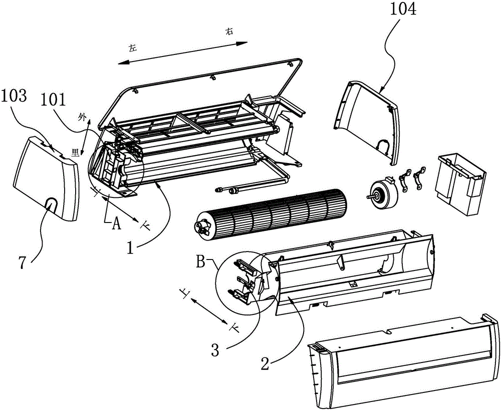
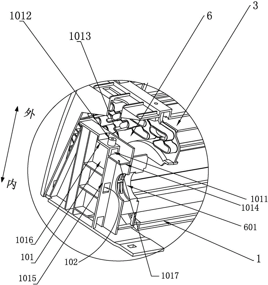
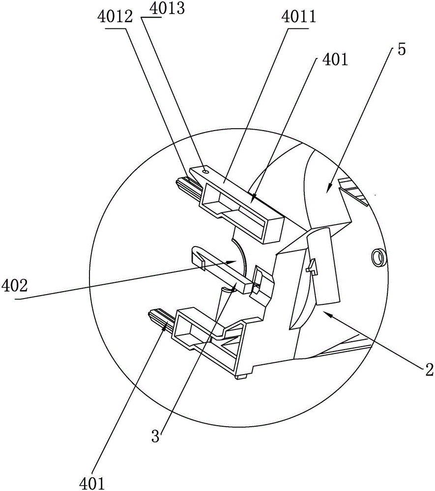
[0026] as attached figure 1 , attached figure 2 and attached image 3 , the base structure of the air conditioner indoor unit of the present invention, it comprises indoor unit chassis 1, has detachable right end plate 103 and detachable left end plate 104; The anti-falling mechanism 3 is arranged on the air guide mechanism 2 and is connected with the chassis 1 of the indoor unit to prevent the air guide mechanism 2 from falling off directly from the chassis 1 of the indoor unit when disassembling and installing the air guide mechanism 2; the hollow structure 6 is arranged on the right end plate 103 or The left end plate 104 or the right end plate 103 and the left end plate 104 are used for connecting pipelines to enter and exit; and the knock-off plate 7 is matched with the hollow structure 6 and detachably installed on the hollow structure 6; wherein, th...


PUM


Abstract

The invention discloses a base structure of an indoor unit of an air conditioner. The base structure comprises an indoor unit chassis (1), an air guide mechanism (2), an anti-dropping mechanism (3), a hollow-out structure (6) and a knock-off plate (7), wherein the indoor unit chassis (1) is equipped with a detachable right end plate (103) and a detachable left end plate (104); the air guide structure (2) can be detachably arranged at the lower end of the indoor unit chassis (1); the anti-dropping mechanism (3) is arranged on the air guide mechanism (2) and is connected and matched with the indoor unit chassis (1), so that the anti-dropping mechanism is prevented from directly dropping from the indoor unit chassis (1); the hollow-out structure (6) is arranged on the right end plate (103) or the left end plate (104) or the right end plate (103) and the left end plate (104) for allowing a connecting pipeline to get in and get out; and the knock-off plate (7) can fit to the hollow-out structure (6) and can be detachably mounted on the hollow-out structure (6). The base structure disclosed by the invention has the advantages that accumulated ash is prevented from affecting comfort of the air conditioner, the air guide mechanism can be prevented from directly dropping in a dismounting process, and the knock-off plate can be directly dismounted to protect the indoor unit of the air conditioner.

Description

technical field [0001] The invention relates to a base structure of an indoor unit of an air conditioner. Background technique [0002] The overall appearance of the indoor unit includes the rear shell of the indoor unit and the front shell of the indoor unit placed on the rear shell of the indoor unit. The rear shell of the indoor unit includes the chassis of the indoor unit, the left end plate and the end plate placed on both sides of the chassis of the indoor The upper cover plate at the upper end of the chassis of the indoor unit and the air guide mechanism placed at the lower end of the chassis of the indoor unit. Among them, the rear shell of the indoor unit is also commonly called the base of the indoor unit. The rear shell of the indoor unit undertakes two important functions. , by setting the installation bracket on the back of the rear shell of the indoor unit (that is, the back of the chassis of the indoor unit), it is used to install the on-hook unit on the wall;...

Claims


Application Information

Patent Timeline
IPC IPC(8): F24F1/00F24F13/20
CPCF24F1/0007F24F13/20
Inventor 倪晓龙秦宪杨勇刚张华中张坤鹏邓楠
Owner AUX AIR CONDITIONING LTD BY SHARE LTD
Learn More