Outdoor self-locking LED display screen

An LED display and self-locking technology, applied in the field of LED screens, can solve the problems of affecting installation time, affecting installation speed, and low installation efficiency of the screen body, and achieve the effects of quick and simple installation, high flatness, and convenient maintenance.

Active Publication Date: 2017-02-15
浙江德广信电子科技股份有限公司
9 Cites 4 Cited by

AI-Extracted Technical Summary

Problems solved by technology

In order to be waterproof and not affect the display, the holes reserved on the module surface need to be arranged in the middle of the four LEDs in a matrix, so the arrangement of the LEDs is displayed, so that it is impossible to achie...

Method used

By self-locking mechanism and unlocking mechanism, the LED display screen is quick and easy to install, easy to maintain, safe, and the flatness of the display surfac...

Abstract

The invention relates to the technical field of LED screens and in particular relates to an outdoor self-locking LED display screen. The outdoor self-locking LED display screen comprises a plurality of modules, a box and a steel frame, wherein the LED display screen is formed by the modules; the box is used for installing the modules; the steel frame is used for installing the box; a self-locking mechanism is arranged between the modules and the box; an unlocking mechanism cooperatively used together with the self-locking mechanism is also arranged between the modules and the box; the self-locking mechanism comprises a plurality of self-locking components; each self-locking component comprises a self-locking area, a self-locking hole, a clamp sheet, a tension spring and a pin rod; the self-locking area is arranged on the backs of the modules; the self-locking hole is formed in the self-locking area; the clamp sheet surrounds the self-locking hole; the tension spring is used for fixing the clamp sheet; the pin rod is fixed with the box, is inserted into the self-locking hole and is provided with a pin slot. The LED display screen has high density, is fast and simple to install and convenient and safe to maintain and has high display surface flatness.

Application Domain

Technology Topic

Image

  • Outdoor self-locking LED display screen
  • Outdoor self-locking LED display screen
  • Outdoor self-locking LED display screen

Examples

  • Experimental program(1)

Example Embodiment

[0027] The technical solutions of the present invention will be further described below in conjunction with the drawings and specific implementations.
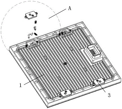
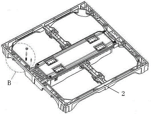
[0028] Such as Figure 1 to Figure 6 As shown, an outdoor self-locking LED display screen includes several modules 1 forming the LED display screen, a box body 2 for installing the module 1 and a steel frame for installing the box body 2. A self-locking mechanism is provided between the module 1 and the box body 2, and an unlocking mechanism that cooperates with the self-locking mechanism is provided between the module 1 and the box body 2.
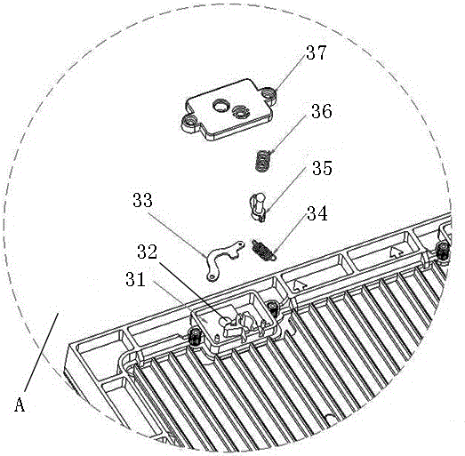
[0029] The self-locking mechanism includes four self-locking components 3 symmetrically arranged on both sides of the module 1. Each self-locking component 3 includes a self-locking area 31 arranged on the back of the module 1, a self-locking hole 32 arranged in the self-locking area 31, a card 33 arranged around the self-locking hole 32, The tension spring 34 is used to fix the card 33 and the pin 21 is fixed to the box 2 and inserted into the self-locking hole 32. The pin rod 21 is provided with a pin groove for clamping the card 33.
[0030] When installing the module, align the self-locking hole 32 of the module 1 with the pin 21 on the box body 2 and press down the module 1 so that the pin 21 on the box body 2 enters the self-locking hole 32. Due to the elasticity of the tension spring 34, the pin 21 will bounce the card 33 outward when entering the self-locking hole 32, so that the pin 21 can smoothly enter the self-locking hole 32. The bottom end of the pin 21 is provided with a pin groove. When the pin 21 completely enters the self-locking hole 32, the card 33 will hit the pin groove. Due to the elasticity of the tension spring 34, when the pin groove of the pin 21 overlaps the card 33, The card 33 will spring into the pin slot to clamp the display module 1 on the box 2.
[0031] The self-locking area 31 is provided with a back cover 37, and the back cover 37 has a through hole for the pin 21 to be inserted into the self-locking hole 32. The card 33 is an arc-shaped strip bent toward the self-locking hole 32, one end is opened with a threaded hole 331 threadedly connected to the screw in the self-locking area 31, and one end of the card 33 can rotate around the fixed screw. The card 33 has a connecting hole 334 connected to the tension spring 34 in the self-locking area 31 at the other end. Due to the elasticity of the tension spring 34, the card 33 can move away from or approach the self-locking hole 32 along with the expansion and contraction of the tension spring 34. The inner arc area of ​​the card 33 is provided with a linkage end 333 connected to the unlocking lever 35. The linkage end 333 is a protrusion extending from the inner arc area of ​​the card 33 toward the unlocking lever 35, and the unlocking lever 35 can act on the linkage end. 333, the card 33 is separated from the pin groove of the pin rod 21. The inner arc area of ​​the card 33 located between the threaded hole 331 and the linkage end 333 is provided with a clamping end 332 that is engaged with the pin groove, and the clamping end 332 is the inner arc area of ​​the card 33. The limiting groove formed between the threaded hole 331 and the protrusion, after the clamping end 332 enters the pin groove, can restrict the card 33 from leaving the pin groove in the left-right direction.
[0032] The unlocking mechanism includes four unlocking components, which are arranged corresponding to the positions of the self-locking components 3. Each of the unlocking components includes an unlocking lever 35 arranged in the self-locking area 31, a compression spring 36 sleeved on the unlocking lever 35, and arranged on the front of the module 1 to cooperate with the unlocking lever 35 Unlock hole used. When the unlocking mechanism is unlocked, a specific needle-shaped removal tool is required, including a pin 41 used in conjunction with the unlocking hole, a fixing plate 42 for fixing the pin 41, and a handle 43 connected to the fixing plate 42.
[0033] There is a ball head at the front end of the unlock lever 35, which corresponds to the slotted holes on both sides of the rear cover 37. When the pin 41 is inserted into the unlock hole when unlocking, push the unlock lever 35 to slide, and the ball head of the unlock lever 35 will be inserted into the rear cover 37 The corresponding limit hole is locked. The diameter of the ball head is larger than the diameter of the hole, but there are grooves on both sides of the hole. Under the external force of the ball head, the aperture will expand to both sides. When the ball head passes, the hole rebounds and clamps the ball head. After unlocking, the unlock lever rebounds.
[0034] The unlocking mechanism also includes four ejector components used in conjunction with the unlocking assembly. The ejector assembly includes an ejector rod 23, an ejector compression spring 22 sleeved on the bottom end of the ejector rod 23, and The hexagonal stud 24 at the top of the ejector rod 23 is described.
[0035] When disassembling the module, insert the four pins 41 of the needle-shaped disassembly tool into the four unlocking holes of the module, and drive the unlocking lever 35 to bounce the card 33 in the lock. When the card 33 is out of the pin groove of the pin lever 21, The ejector assembly between the module 1 and the box body 2 ejects the module 1 from the slim surface of the box body 2 through an ejector compression spring 22. Because the unlocking mechanism is plug-in type, it only needs a small aperture to achieve a higher density of outdoor LED display.
[0036] The self-locking mechanism and the unlocking mechanism make the installation of the LED display screen quick and simple, convenient and safe to maintain, and the display surface is high in flatness. The cabinet 1 is made of aluminum die-casting. The fixing structure points of the self-locking mechanism are injection molded with high precision.
[0037] A second self-locking mechanism is provided between the box body 2 and the steel frame. The second self-locking mechanism includes four second self-locking components, and each of the second self-locking components includes a second self-locking area provided on the back of the box 2 and is provided in the second self-locking area The second self-locking hole inside, the second card arranged around the second self-locking hole, the second tension spring used to fix the second card, and the second tension spring fixed with the steel frame for inserting the first A second pin with two self-locking holes, and the second pin is provided with a second pin groove.
[0038] When the box 2 is assembled, the second self-locking hole of the box 2 corresponds to the second pin with the second pin groove on the steel frame, and the box 2 is pushed in so that the second pin penetrates into the second lock hole to lock The second card inside is opened. When the second pin slot of the second pin rod coincides with the second card, the second card springs into the second pin slot to clamp the box 2 to the steel frame. The second self-locking mechanism on the box body 2 has no unlocking mechanism. After the box body 2 is installed on the steel frame, it will not be disassembled before the end of the life of the display screen.
[0039] The above-mentioned embodiments only describe the preferred embodiments of the present invention, and do not limit the concept and scope of the present invention. Without departing from the design concept of the present invention, various modifications and improvements made by those skilled in the art to the technical solution of the present invention should fall within the protection scope of the present invention. The technical content claimed by the present invention has been all It is stated in the claims.

PUM

no PUM

Description & Claims & Application Information

We can also present the details of the Description, Claims and Application information to help users get a comprehensive understanding of the technical details of the patent, such as background art, summary of invention, brief description of drawings, description of embodiments, and other original content. On the other hand, users can also determine the specific scope of protection of the technology through the list of claims; as well as understand the changes in the life cycle of the technology with the presentation of the patent timeline. Login to view more.

Similar technology patents

Rock foundation upper brake bottom horizontal wide seam and filling components

InactiveCN103806418AEasy to factoryEasy and quick installationBarrages/weirsBuilding constructionWater brake
Owner:WATER RESOURCES RES INST OF SHANDONG PROVINCE

Classification and recommendation of technical efficacy words

  • Easy maintenance
  • Easy and quick installation

High clearance vehicle

InactiveUS6454294B1Big gapEasy maintenanceAgricultural machinesVehicle body-frame connectionsSpray nozzleHinge angle
Owner:CNH IND AMERICA LLC

Method for mounting large-area refractory fiber module

ActiveCN102425949AEasy and quick installationGood appearance qualityMonolithic liningsWrenchEngineering
Owner:CHINA FIRST METALLURGICAL GROUP

Bamboo rod system structure pedestrian arch bridge

InactiveCN102061661AEasy to process and constructEasy and quick installationBridge structural detailsArch-type bridgeHandrailSystem structure
Owner:湖南博世安新技术有限公司
Why Eureka
Try Eureka