
A wire pulling device for power line construction

A wire pulling device and power line technology, applied in the direction of overhead lines/cable equipment, etc., can solve the problems of no shock absorption function, short service life, damage to wire pulling auxiliary devices, etc.

Inactive Publication Date: 2017-11-21
PENGLAI POWER SUPPLY CO OF STATE GRID SHANDONG ELECTRIC POWER CO
View PDF4 Cites 0 Cited by
  • Summary
  • Abstract
  • Description
  • Claims
  • Application Information

AI Technical Summary

Problems solved by technology

[0002] During the construction of power lines, it is necessary to pull and tighten the power cables to complete the laying of the power cables and adjust the tension of the power cables. When pulling the power cables, the use of pulling devices is essential. The auxiliary device can ensure that the cable is pulled out conveniently. The currently used cable guide device has a simple structure, low strength, and is easy to fall off, and it is easy to rust and corrode after a long period of use and cause damage. The service life is short. Shock absorption function, when the power cable is too long and the pressure is too high, it is easy to cause stress concentration and damage to the auxiliary wire pulling device. Now a wire auxiliary device specially designed for the above problems is needed to solve the above problems

Method used


Image

  • A wire pulling device for power line construction
  • A wire pulling device for power line construction
  • A wire pulling device for power line construction

Examples


Embodiment Construction

[0016] The technical solutions in the embodiments of the present invention will be clearly and completely described below in conjunction with the accompanying drawings in the embodiments of the present invention. Obviously, the described embodiments are only a part of the embodiments of the present invention, rather than all the embodiments. Based on the embodiments of the present invention, all other embodiments obtained by those of ordinary skill in the art without creative work shall fall within the protection scope of the present invention.

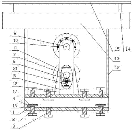
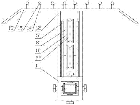
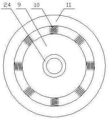
[0017] See Figure 1-4 , The present invention provides a technical solution: a wire drawing device for power line construction, comprising a mounting frame 1, a set of clamping bolts 2 and a set of positioning bolts 3 are alternately worn on the four walls of the mounting frame 1, and the clamping bolts 2 ends The upper part of the mounting frame 1 is provided with a splint 4, the upper part of the mounting frame 1 is provided with a sh...


PUM


Abstract

The invention discloses a cable drawing device for electric power line construction, which comprises an installation rack, and is characterized in that four walls of the installation rack are alternatively provided with a set of clamping bolts and a set of positioning bolts in a penetrating manner, the end part of each clamping bolt is provided with a clamping plate, the upper part of the installation rack is provided with a shaft bracket, the middle part of the shaft bracket is slidably provided with a sliding block, the sliding block is provided with a lower shaft, the upper part of the installation rack is provided with an upper shaft, both the lower shaft and the upper shaft are provided with an inner wheel in a penetrating manner, each inner wheel is matched with a corresponding outer wheel through a set of damping springs, both ends of the installation rack are provided with a vertical column, the top ends of the vertical columns are connected with a rain sheltering plate, the upper part of the rain sheltering plate is provided with a set of vertical rods, and the vertical rods are connected with a cross arm. The cable drawing device for electric power line construction is simple to operate, extremely high in fixation reliability, and capable of adjusting the distance between the upper shaft and the lower shaft according to actual requirements. In addition, the cable drawing device for electric power line construction has a damping effect in use, can avoid occurrence of a stress concentration phenomenon, reduces the damage probability of the shaft bracket, and prolongs the service life of the device.

Description

Technical field [0001] The invention relates to the field of wire pulling devices, in particular to a wire pulling device for power line construction. Background technique [0002] In the construction of power lines, it is necessary to traction and tighten the power cables to complete the laying of the power cables and adjust the tension of the power cables. When traction power cables, the use of cable pulling devices is essential. The auxiliary device can ensure that the cable can be easily pulled out. The currently used cable guide device has a simple structure, low strength, easy to fall off, and it is easy to rust and corrode after a long time of use, causing damage, and has a short service life. With the function of shock absorption, when the power cable is too long and the pressure is too high, it is easy to cause stress concentration phenomenon and damage to the cable auxiliary device. A cable auxiliary device specially designed for the above problems is needed to solve th...

Claims


Application Information

Patent Timeline
Patent Type & Authority Patents(China)
IPC IPC(8): H02G1/04
CPCH02G1/04
Inventor 纪广欣门晓亮李晓辉何建忠葛承鹏孙兆龙于文波于恒泉宫恩臣张庆生黄涛丛北亭方振伟牟平江宋宇王德毅刘兆旺张刚张旭东葛承春王家超张大军
Owner PENGLAI POWER SUPPLY CO OF STATE GRID SHANDONG ELECTRIC POWER CO
Learn More