Police oblique-photography real 3D platform system and interface system thereof
A technology of oblique photography and 3D platform, applied in the field of 3S, can solve the problems of inaccurate geographical distribution data of manual real 3D models, inability to deeply integrate the public security system, and low rapid response capability of public security organs' combat command.
- Summary
- Abstract
- Description
- Claims
- Application Information
AI Technical Summary
Problems solved by technology
Method used
Image

Examples
Embodiment 1
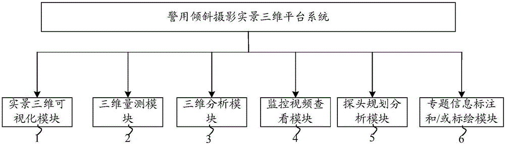
[0033] Such as figure 1 As shown, the present embodiment provides a real-scene 3D platform system for police oblique photography. The real-scene 3D platform system for police oblique photography is based on the real-scene 3D model obtained by oblique photography technology. The real-scene 3D platform system for police oblique photography includes: real-scene 3D visualization Module 1, 3D measurement module 2, 3D analysis module 3, monitoring video viewing module 4, probe planning and analysis module 5, and thematic information labeling and / or plotting module 6; the real-scene 3D visualization module 1 is used for multi-dimensional real-scene 3D model Visual display of layers and multi-level blocks; 3D measurement module 2 is used to measure the real 3D model of the visible area; 3D analysis module 3 is used to analyze the real 3D model of the visible area; monitoring video viewing Module 4 is used to obtain the monitoring probe distribution data in the database, and accurately...
Embodiment 2
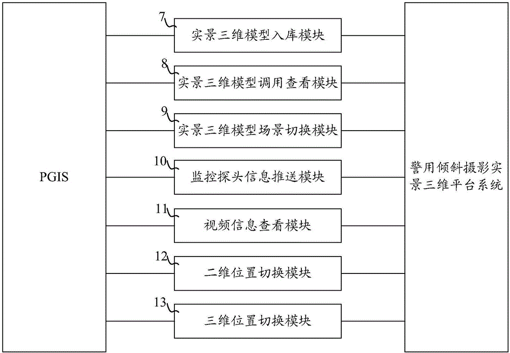
[0050] Such as image 3 As shown, this example provides a police oblique photography real-scene 3D platform interface system, which is used to interface the police oblique photography real-scene 3D platform system with PGIS. The interface system of the police oblique photography real-scene 3D platform includes a real-scene 3D model storage module 7, a real-scene 3D model calling and viewing module 8, a real-scene 3D model scene switching module 9, a monitoring probe information push module 10, a video information viewing module 11, and a two-dimensional Position switching module 12 and three-dimensional position switching module 13; Wherein, real-scene three-dimensional model warehouse-in module 7, is used for obtaining the information in the database that links to each other with PGIS, generates real-scene three-dimensional model data recording table; The 3D model warehousing module is connected to 7, and is used to record the real-scene 3D model data record table (the real-s...
Embodiment 3
[0054] This example provides an integration method of the PGIS or video surveillance system in the prior art and the three-dimensional platform system for police oblique photography.
[0055] First, the integration method at the data level is introduced: for the correspondence between 2D data and 3D data, the main method is to correspond the elements in the 3D scene to the specific vector graphics or model points in the 2D layer, and perform data query, data During the update operation, the consistency of the two-dimensional and three-dimensional data is guaranteed through this correspondence.
[0056]The specific implementation method is to associate the 3D data with the data of the 2D layer in the data structure. Therefore, we set the number of the 3D element as the field attribute of the corresponding 2D layer element. The mapping between 3D elements and 2D elements is connected through the 3D element number and the 2D layer corresponding to the 3D element number; while the...
PUM
 Abstract
Description
Claims
Application Information
PatSnap Eureka turns technology decisions into work you can execute. Powered by our Innovation Knowledge Graph, it runs expert workflows across engineering, life sciences, materials and intellectual property. Get your review-ready output in minutes.


