Puncture needle positioning support for computed tomography (CT) machine

A technology for positioning brackets and puncture needles, applied in the field of medical instruments, can solve problems such as difficult to control the location of lesions, difficult to locate lesions, and damage to human tissue

Active Publication Date: 2017-02-22
THE SECOND HOSPITAL AFFILIATED TO WENZHOU MEDICAL COLLEGE
View PDF5 Cites 7 Cited by
  • Summary
  • Abstract
  • Description
  • Claims
  • Application Information

AI Technical Summary

Problems solved by technology

[0004] However, during the inspection process, it is difficult to control the location of the lesion, especially when the lesion is small, it is even more difficult to accurately locate the lesion. The movement process of the stent in the prior art is too mechanized, and each action is limi

Method used


Image

  • Puncture needle positioning support for computed tomography (CT) machine
  • Puncture needle positioning support for computed tomography (CT) machine
  • Puncture needle positioning support for computed tomography (CT) machine

Examples


Embodiment 1

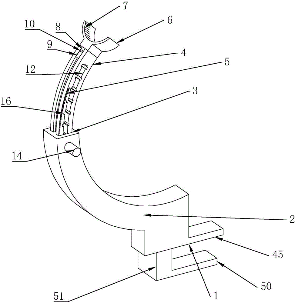
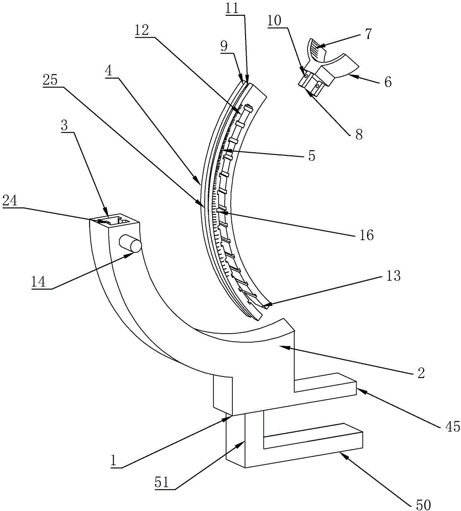
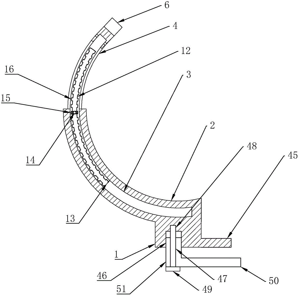
[0037] A puncture needle positioning bracket for a CT machine in this embodiment includes a base 1, on which a mounting block 2 is arranged, the mounting block 2 is at least a quarter circular, and the mounting block 2 is provided with a sliding groove 3, and a sliding block 4 is slidably connected in the sliding groove 3, and the shape of the sliding block 4 is at least a quarter of a circle, and the sliding block 4 is provided with a The first scale 5, the end of the sliding block 4 protruding from the sliding groove 3 is provided with a cushion 6, the cushion 6 is provided with a second scale 7 for indicating the angle, and the inner wall of the sliding groove 3 is provided with a sliding mechanism, The sliding mechanism is in contact with the sliding block 4, the cushion 6 is provided with a molding 8, the sliding block 4 is provided with a slot 9 for inserting the molding 8, and the molding 8 is provided with a first screw thread A second threaded hole 11 concentric with ...

Embodiment 2

[0043] Embodiment two: according to Figure 4 as shown,

[0044] On the basis of Embodiment 1, the control mechanism includes a baffle plate 18 arranged on the positioning shaft 14, and a first spring 19 is provided on the baffle plate 18 and the inner wall of the slide groove 3, and one end of the first spring 19 It is connected with the baffle plate 18, and the other end is connected with the inner wall of the sliding groove 3. When the positioning shaft 14 is pressed outside the mounting block 2, the positioning block 15 on the positioning shaft 14 breaks away from the positioning tooth 16 and enters the accommodating cavity 17. The first spring 19 keeps the positioning block 15 located in the positioning tooth 16 .

[0045] During use, under normal conditions, under the action of the first spring 19, the chain ends of the first spring 19 are respectively connected to the baffle plate 18 and the inner wall of the sliding groove 3, so that the positioning block 15 is contin...

Embodiment 3

[0046] Embodiment three: according to Figures 6 to 7 said

[0047] On the basis of Embodiment 1, the sliding mechanism further includes a roller 26, a first installation groove 27 is provided at the inner and outer diameter of the sliding groove, and a first installation plate 28 is arranged in the first installation groove 27 , the two sides of the first installation plate 28 and the first installation groove 27 are provided with an extension plate 29, the extension plate 29 is provided with a rotating shaft 30, and the roller 26 is arranged on the rotating shaft 30. The extension plate 29 is provided with a track groove 32, and the rotating shaft 30 is located in the track groove 32. The rotating shaft 30 is connected with a rubber extension spring 31 that keeps the rotating shaft 30 away from the first mounting plate 28. The rubber extension spring One end of 31 is fixed on the rotating shaft 30 , and the other end is fixed on the first mounting plate 28 .

[0048] The s...


PUM


Abstract

The invention discloses a puncture needle positioning support for a computed tomography (CT) machine. The puncture needle positioning support comprises a base, the base is provided with an installing block, the installing block is in an at least 1/4 ring shape, a sliding groove is formed in the installing block, a sliding block is slidably connected in the sliding groove and is in an at least 1/4 ring shape, the sliding block is provided with first scales for indicating an angle, one end of the sliding block extending out of the sliding groove is provided with a back cushion, and the back cushion is provided with second scales for indicating an angle. In the movement process, it is fully guaranteed that surrounding tissues and focus tissues are not damaged by a puncture needle. The puncture needle positioning support can also adapt to manual operation.

Description

technical field [0001] The invention relates to a medical instrument, in particular to a positioning bracket for a puncture needle used in a CT machine. Background technique [0002] Puncture is to puncture the puncture needle into the human body to draw out the lesion for testing. At the same time, if necessary, drugs can be administered to the lesion to treat the lesion. [0003] The puncture needle is a common tool used in the puncture process, especially in some inspection items, which need to be checked by the puncture needle, such as the position of the tumor. In the prior art, the Chinese patent with the application number CN201420366671.5 discloses a puncture device based on CT machine images. The main arm of the main arm is also provided with a rotating stretching frame, one end of the main arm is provided with a main arm seat, the main arm seat is connected with a rotatable and stretchable main arm rod, and the other end of the main arm rod is provided with a posi...

Claims


Application Information

Patent Timeline
IPC IPC(8): A61B17/34A61B6/03A61B50/22
CPCA61B6/032A61B17/3403
Inventor 徐雷程建敏
Owner THE SECOND HOSPITAL AFFILIATED TO WENZHOU MEDICAL COLLEGE
Why Eureka
Try Eureka