Speed-controllable backboard release device for obstetric bed

A release device and backboard technology, applied in the field of medical devices, can solve the problems of long order cycle, poor control of backplane descending speed, high price, etc., to achieve stable release speed, overcome changing load, and strong resistance to load The effect of the ability to change

Active Publication Date: 2018-05-29
SHANDONG LEWIN MEDICAL EQUIP CO LTD
View PDF9 Cites 0 Cited by
  • Summary
  • Abstract
  • Description
  • Claims
  • Application Information

AI Technical Summary

Problems solved by technology

However, because the electric push rod used needs to be imported from abroad, the order cycle is long and the price is high, which brings a lot of inconvenience to the manufacturer.
[0004] At present, there is also an electric push rod with a quick release function on the market. Since this electric push rod only relies on the friction between the screw nut to prevent the movement of the push rod when the quick release is opened, it cannot be well controlled. The falling speed of the backplane, and when the load on the backplane is increased, it will cause the backplane to fall faster

Method used


Image

  • Speed-controllable backboard release device for obstetric bed
  • Speed-controllable backboard release device for obstetric bed
  • Speed-controllable backboard release device for obstetric bed

Examples


specific Embodiment 1

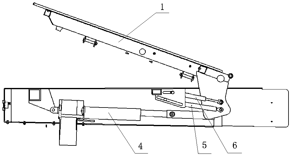
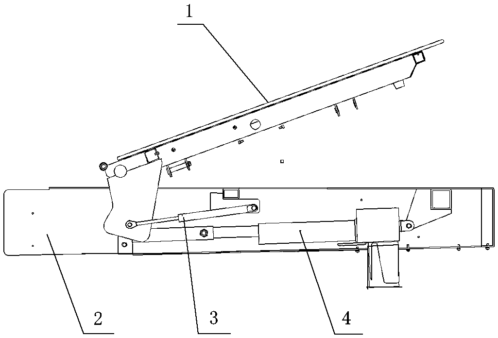
[0022] The weight of backplane 1 is 5KG, the load of backplane 1 is 35KG, the damping value of upper gas spring 6 is 250N, the damping value of lower gas spring 5 is 250N, the damping value of damping rod 3 is 480N, and the maximum backplane rotation angle is 65°;

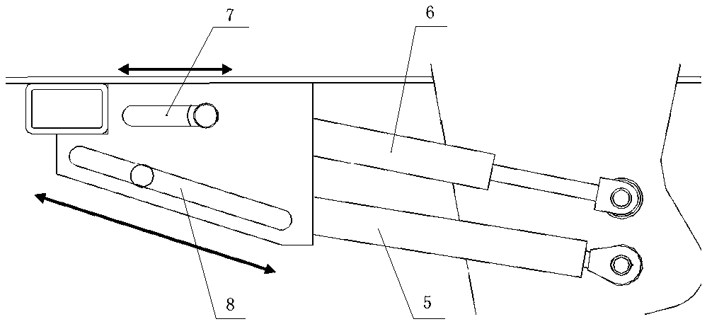
[0023] When adjusting the backplane 1 to the maximum backplane angle, the cylindrical rollers of the sliding structure hinged with the upper gas spring 6 and the lower gas spring 5 are respectively in contact with the starting points of the upper chute 7 and the lower chute 8, and the upper gas spring 6 and the lower gas spring 5 is the shortest length. When the backboard 1 falls from the maximum backboard rotation angle to an angle of 48° with the horizontal plane, the cylindrical roller of the sliding structure hinged with the upper gas spring 6 contacts the end point of the upper chute 7, and the upper gas spring 6 starts At this time, when the backboard 1 falls from an angle of 48° to the horizontal plane to an ...

specific Embodiment 2

[0025] The weight of backplane 1 is 5KG, the load of backplane 1 is 35KG, the damping value of upper gas spring 6 is 250N, the damping value of lower gas spring 5 is 250N, the damping value of damping rod 3 is 480N, and the maximum backplane rotation angle is 65°;

[0026] When adjusting the backplane 1 to the maximum backplane angle, the cylindrical rollers of the sliding structure hinged with the upper gas spring 6 and the lower gas spring 5 are respectively in contact with the starting points of the upper chute 7 and the lower chute 8, and the upper gas spring 6 and the lower gas spring 5 is the shortest length. When the backboard 1 falls from the maximum backboard rotation angle to an angle of 42° with the horizontal plane, the cylindrical roller of the sliding structure hinged with the upper gas spring 6 contacts the end point of the upper chute 7, and the upper gas spring 6 starts At this time, when the backboard 1 falls from an angle of 42° to the horizontal plane to an ...


PUM


Abstract

A back board releasing device controllable in obstetric sickbed speed comprises a back board, a frame, damp rods, an electric push rod, lower air springs, upper air springs, an upper sliding groove and a lower sliding groove. A pair of connecting plates perpendicular to the back board is arranged in the middle of the lower surface of one end of the middle, close to the frame, of the back board, and the end provided with the connecting plates, of the back board is further connected with the frame through a rotary shaft. The back board releasing device is characterized in that the connecting plates are hinged to the front end of the electric push rod through connecting structures, the rear end of the electric push rod is hinged to the frame, the lower air springs and the upper air springs are hinged to one side face of the connecting plates, a sliding structure is hinged to the other end of each lower air spring and the other end of each upper air spring respectively, and the sliding structures are matched with plug plates fixedly arranged on the frame in a paired mode. The damp rods are hinged to the other side face of each connecting plate, and the other end of each damp rod is in hinged connection with the frame. The back board releasing device can control the back board releasing speed in a set range and meanwhile has strong load change resistance capability.

Description

technical field [0001] The invention relates to the technical field of medical devices, in particular to a speed-controllable backboard release device for an obstetric bed. Background technique [0002] At present, the backboards of the obstetric and sickness integrated beds on the market all have the function of CPR, that is, the backboard on which the patient lies can be quickly leveled, and the patient can be given emergency cardiopulmonary resuscitation. However, this quick release occurs when the patient is already lying on the bed, so too fast a speed will cause a serious impact and cause unnecessary harm to the patient, especially the puerpera. Therefore, the speed control of the rapid release of the backboard has also become an important research project of the CPR function. [0003] The current mainstream solution for speed control is to do rotation damping in the electric push rod that drives the movement of the back plate, so as to control the descending speed of...

Claims


Application Information

Patent Timeline
Patent Type & Authority Patents(China)
IPC IPC(8): A61G13/08A61G13/10
CPCA61G13/0009A61G13/08A61G13/10A61G2200/12A61G2203/14A61G2203/70
Inventor 孔新华石成新韩乃国
Owner SHANDONG LEWIN MEDICAL EQUIP CO LTD
Why Eureka
Try Eureka