Golf ball bag provided with automatically lifting club protection cover

A golf bag and automatic lifting technology, which is applied to golf club bags, golf balls, rackets, etc., can solve the problems of occupying outer barrel space, high cost, and small selection range for the surface smoothness of the club protective cover. Achieve the effect of improving grade, small space and cost saving

Active Publication Date: 2017-02-22
东莞市宏祥运动制品有限公司
View PDF14 Cites 15 Cited by
  • Summary
  • Abstract
  • Description
  • Claims
  • Application Information

AI Technical Summary

Problems solved by technology

In this way, the greater frictional force makes the user need to spend more force when pulling or pressing. If the frictional force is too large, the entire ball bag will be lifted when pulling upwards
[0006] 2. The space utilization rate in the outer barrel is low
[0007] Because the above-mentioned sliding mechanism is installed between the inner wall of the club protective cover and the bottom shell of the outer barrel, many longer slide bars will take up a lot of space in the outer barrel from the upper part of the outer barrel to the bottom. Therefore, the space utilization rate in the outer bucket will be reduced
[0008] 3. Since the club protection cover is always in a raised position when the rod is not in use, only when there is a certain friction between the outer wall of the club protection cover and the inner wall of the outer barrel, the club protection cover can be in a suspended state. Therefore, The outer surface of the club protective cover and outer barrel always needs to be wrapped with a decorative layer such as leather, canvas or fiber cloth. Therefore, during production, the material, softness and hardness of the material, color and club protection The surface smoothness of the cover has a small selection range

Method used


Image

  • Golf ball bag provided with automatically lifting club protection cover
  • Golf ball bag provided with automatically lifting club protection cover
  • Golf ball bag provided with automatically lifting club protection cover

Examples


Embodiment 1

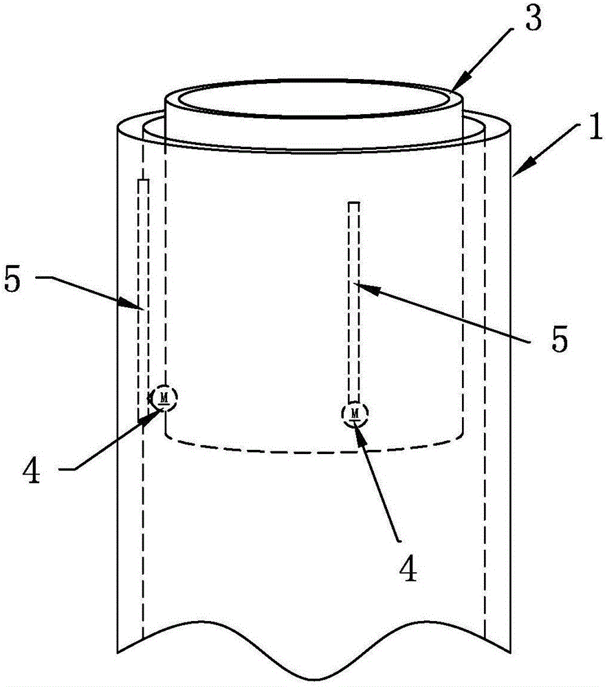
[0093] Such as Figure 7 , 10 As shown, the driving device 4 includes a motor 41 and a deceleration assembly 42, the motor 41 is fixedly connected to the lower part of the club protective cover 3, and the transmission mechanism 5 is composed of a rack 51 and a gear rack vertically arranged on the inner wall of the outer barrel 1. The gear 52 arranged on the outer wall of the club protective cover 3 and meshed with the rack 51 is formed, and the gear 52 is connected to the motor 41 through the reduction assembly 42 . When rising, the motor 41 drives the gear 52 to crawl upwards along the rack 51 through the reduction assembly 42. Since the rack 51 is fixed, there is a gap between the gear 52, the reduction assembly 42, the motor 41 and the club protective cover 3 It is rigidly connected (that is, the gear 52, the deceleration assembly 42, and the motor 41 have no displacement relative to the cue protection cover 3), therefore, the upward movement of the gear 52 also drives the...

Embodiment 2

[0095] Such as Figure 7 , 11 The difference from Embodiment 1 is that the transmission mechanism 5 in this embodiment is composed of a screw 53 and a nut 54 sleeved on the screw 53, and the screw 53 is vertically arranged on the outside of the club protective cover 3 Correspondingly, the nut 54 is fixedly connected to the bracket 43 provided on the inner wall of the tub 1, and the upper end of the screw rod 53 is connected to the motor 41 through the reduction assembly 42, and there is a rigid connection structure therebetween. Because the nut 54 is fixed, when rising, the motor 41 drives the screw rod 53 to rotate through the deceleration assembly 42, and the rotating screw rod 53 moves up relative to the nut 54 and drives the club protective cover 3 to move upward.

[0096] This structure hinders the appearance when the club protective cover 3 is moved up to the screw rod 53 and the deceleration assembly 42 is exposed outside.

Embodiment 3

[0098] Such as Figure 7 , 12 As shown, the difference from Embodiment 2 is that the screw rod 53 in this embodiment is vertically arranged on the inner side of the club protective cover 3, and correspondingly, the nut 54 is fixedly connected to the inner wall of the outer barrel 1. On the bracket 43 , the upper end of the screw rod 53 is connected with the driving motor 41 . The lifting principle of the club protective cover 3 in this embodiment is the same as that in Embodiment 2. Compared with Embodiment 2, it has the advantage of neat appearance and beautiful appearance. The reason is as follows: since the screw rod 53 is concealed in the club protective cover 3, no matter whether the club protective cover 3 rises or falls, the exposed screw rod 53 will not be seen from the outside. outside.

[0099] 2. The driving device 4 is set on the inner wall of the outer tub 1


PUM


Abstract

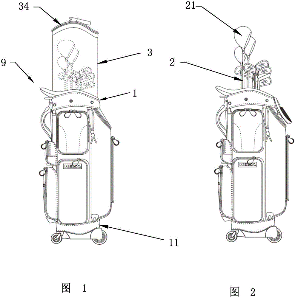
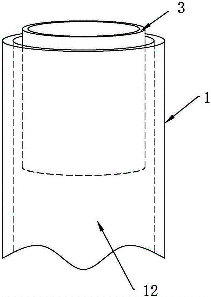
Provided is a golf ball bag small in occupied space and capable of making a club protection cover automatically move up and down in the axial direction of an outer cylinder. A driving device capable of driving the club protection cover to move vertically is fixedly arranged and located on the lower portion of the club protection cover in the outer cylinder or the inner wall of the outer cylinder. A driving mechanism for transferring kinetic energy output by the driving device to the club protection cover is arranged between the inner wall of the outer cylinder and the outer wall of the club protection cover or on the inner side of the club protection cover. The golf ball bag is further provided with a control circuit controlling work of the driving device and a switching part for starting or turning off the control circuit. The golf ball bag makes vertical movement of the club protection cover automatic, and the grade of the golf ball bag is greatly improved. In addition, the complicated operation brought to a user due to upward lifting or downward pressing exerted to the club protection cover can be also avoided. The occupied space in the outer cylinder is small, and accordingly the damage phenomenon caused by often bump and friction between a club and a supporting device in the prior art is avoided.

Description

technical field [0001] The invention relates to a golf bag, in particular to a golf bag with a club protective cover that can be automatically lifted. Background technique [0002] The applicant's Chinese invention patent (application number: 201110327020.6, date of application is October 25, 2011, titled "golf bag") discloses a ball that can move up and down in the outer barrel of the golf bag. The technical scheme of the rod protection cover, when not playing at ordinary times, the club protection cover is pulled out from the outer barrel and the club heads of the clubs in the outer barrel are covered, and then the top cover zipper that is arranged on the club protection cover is pulled Live, all clubs can be sealed in the outer barrel. When in use, the zipper of the top cover is pulled open, and the club head is exposed by pressing down on the club protective cover so that the club can be easily taken out from the upper port of the club protective cover. [0003] But it...

Claims


Application Information

Patent Timeline
Patent Type & Authority Applications(China)
IPC IPC(8): A63B55/40A63B102/32
CPCA63B55/40
Inventor 张爱平
Owner 东莞市宏祥运动制品有限公司
Why Eureka
Try Eureka