Impregnating equipment and method

A technology of impregnation equipment and impregnation medium, which is applied in the field of impregnation equipment and impregnation, can solve the problems of high cost, high production cost, and time-consuming, and achieve the effect of saving time and reducing production cost

Active Publication Date: 2017-02-22
湖南顶立科技股份有限公司
View PDF6 Cites 0 Cited by
  • Summary
  • Abstract
  • Description
  • Claims
  • Application Information

AI Technical Summary

Problems solved by technology

[0003] At present, due to some limitations in the structural design of the existing impregnation equipment, when using the existing impregnation equipment to impregnate workpieces, the impregnation chamber of the impregnation equipment must be pretreated when each batch of workpieces is processed. (such as vacuuming, heating, pressurizing), then heat the workpiece and the impregnating medium to the specified temperature in the impregnation chamber, then place the workpiece in the impregnation medium for impregnation, and then completely cool the workpiece in the impregnation chamber of the impregnation equipment , and finally take out the cooled workpiece. In this process, the actual time spent on pressure impregnation of the workpiece only accounts for 1 / 6 to 1 / 3 of the entire workpiece impregnation cycle, while a large amount of other time is spent on the pre-heating and In the post-cooling and cooling, it takes a very long time for each batch of workpieces to be impregnated, and the processing speed of the workpieces is very low. When a large number of workpieces need to be processed, it takes a lot of time; in addition, the heating set in the existing impregnation equipment Components and insulation materials need to be heated and cooled again after the treatment of the previous batch of workpieces. At the same time, the impregnation medium set in the impregnation equipment also needs to be heated and cooled again. Such a large amount of heat is directly lost without acting on the impregnation of the workpieces, and the production cost very high

Method used


Image

  • Impregnating equipment and method
  • Impregnating equipment and method
  • Impregnating equipment and method

Examples


Embodiment Construction

[0031] In order to enable those skilled in the art to better understand the technical solutions in the present application, the technical solutions in the embodiments of the present application will be clearly and completely described below in conjunction with the drawings in the embodiments of the present application. Obviously, the described The embodiments are only some of the embodiments of the present application, but not all of them.

[0032] Based on the embodiments in this application, all other embodiments obtained by persons of ordinary skill in the art without creative efforts shall fall within the scope of protection of this application.

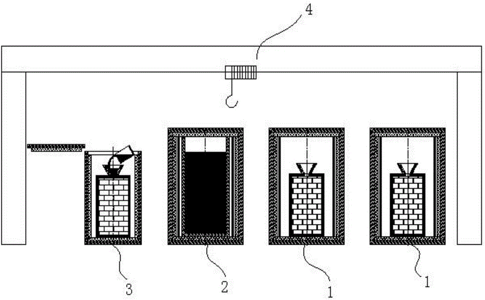
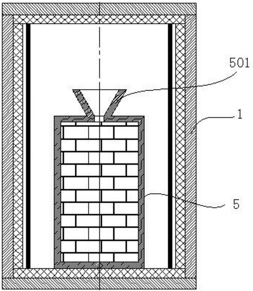
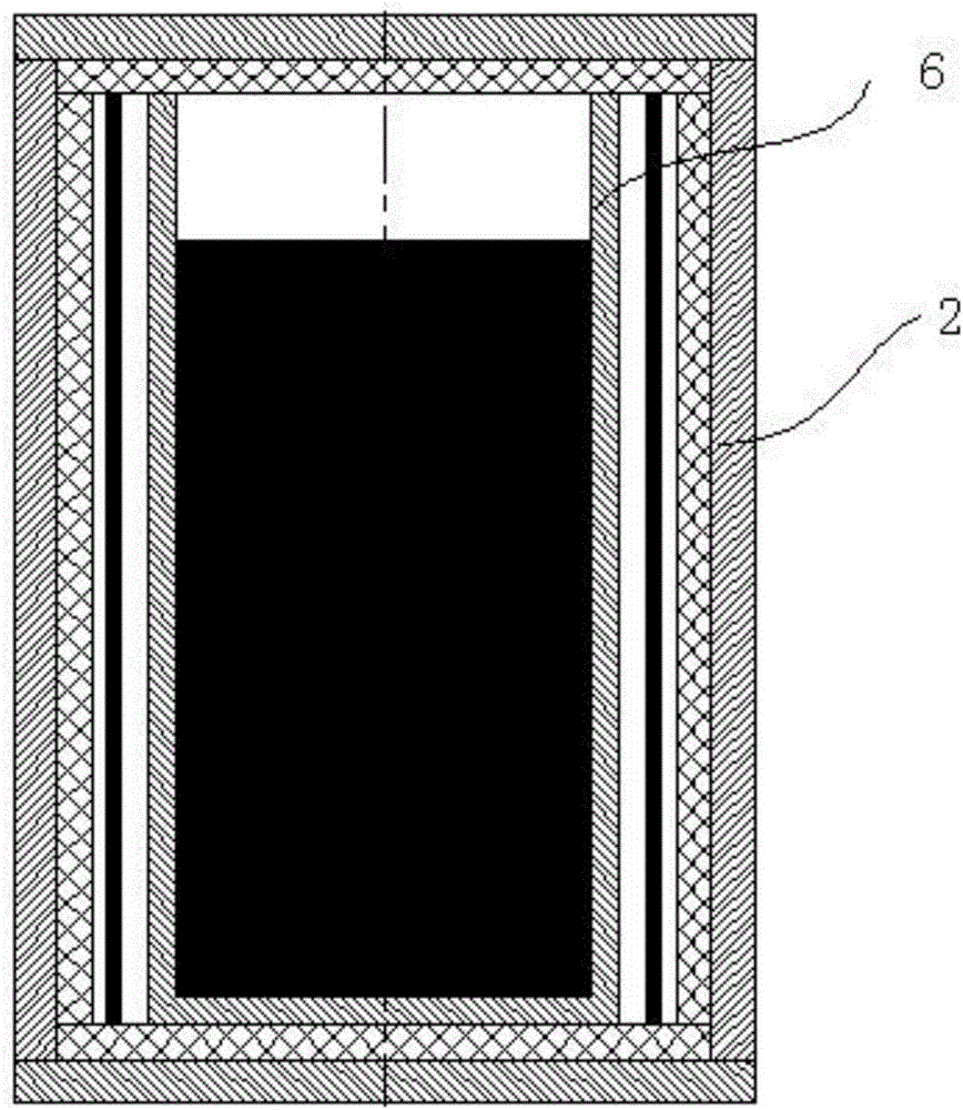
[0033] see Figure 1 to Figure 4 , Figure 1 to Figure 4 A specific embodiment of the present invention is provided, wherein, figure 1 It is a schematic diagram of the overall structure of an impregnation device according to an embodiment of the present invention; figure 2 It is an enlarged schematic diagram of a heating furn...


PUM


Abstract

The invention discloses impregnating equipment used for impregnating workpieces. The impregnating equipment comprises a heating furnace, a smelting furnace, an impregnating furnace and a hoisting mechanism, wherein the heating furnace is used for providing a space for heating the workpieces, the smelting furnace is arranged on the outer side of the heating furnace and used for providing a space for smelting impregnating media, the impregnating furnace is arranged on the outer side of the heating furnace and comprises a furnace shell, a working cavity arranged inside the furnace shell and a pressure control system connected to the working cavity, the impregnating furnace is used for providing a space for impregnating the workpieces, and the hoisting mechanism is connected to the heating furnace, the smelting furnace and the impregnating furnace and used for transferring the positions of the workpieces and the impregnating media. The invention further provides an impregnating method. According to the impregnating equipment and method, continuous bath processing of the workpieces can be effectively achieved, the workpiece processing speed is improved, meanwhile, the energy loss can be effectively reduced, and the production cost is reduced.

Description

technical field [0001] The invention relates to the field of material processing equipment, more specifically, to an impregnation equipment and an impregnation method. Background technique [0002] The impregnation method is a method commonly used to improve the performance of carbon-based composite materials or ceramic-based composite materials. The metal ions in the impregnation impregnate the material to be treated and penetrate into its inner surface to form a material with superior performance. Among them, the impregnated metal medium generally includes aluminum, copper, titanium and high-temperature alloys. Because impregnation can greatly enhance the performance of materials, impregnation is widely used in aerospace, military and national defense, electronic information, rail transit and other fields. Specifically, when using the impregnation method to process materials, it is often necessary to rely on special impregnation equipment. [0003] At present, due to som...

Claims


Application Information

Patent Timeline
IPC IPC(8): B22D23/04
CPCB22D23/04
Inventor 胡高健胡祥龙戴煜
Owner 湖南顶立科技股份有限公司
Why Eureka
Try Eureka