

Safe concrete pneumatic vibration rod
A pneumatic vibration and concrete technology, which is applied to clay preparation devices, chemical instruments and methods, cement mixing devices, etc., can solve problems such as risks, high safety risks, and huge problems caused by staff, so as to reduce working hours and improve safety performance , the effect of improving practicality
- Summary
- Abstract
- Description
- Claims
- Application Information
AI Technical Summary
Problems solved by technology
Method used
Image

Examples
Embodiment 1
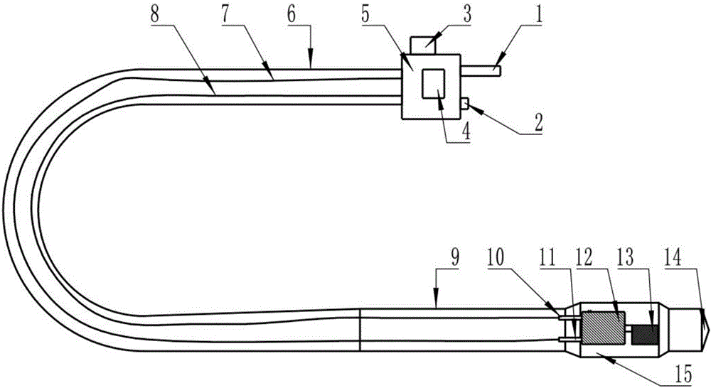
[0024] Such as figure 2 As shown, a safe concrete pneumatic vibrator is mainly composed of shell 5, working hose 6, working hard tube 9, pneumatic device 12, pneumatic device shell 15, eccentric wheel 13, and insert cone 14; shell 5 is cylindrical Shell-like structure, one end of the shell 5 is provided with a vibrating rod inlet 1 and a vibrating rod exhaust port 2, and a switch 3 and a control knob 4 are provided on the side of the shell 5; One end of the hard tube 9 is connected, and the other end of the working hard tube 9 is connected to the insert cone 14 through the pneumatic device housing 15; the pneumatic device 12 and the eccentric wheel 13 are arranged inside the pneumatic device housing 15, and the rotating shaft of the pneumatic device 12 and the eccentric wheel 13 The pneumatic device 12 is provided with the pneumatic device exhaust interface 10 and the pneumatic device intake interface 11; the vibrating rod intake port 1 is connected to the pneumatic device inta...
Embodiment 2
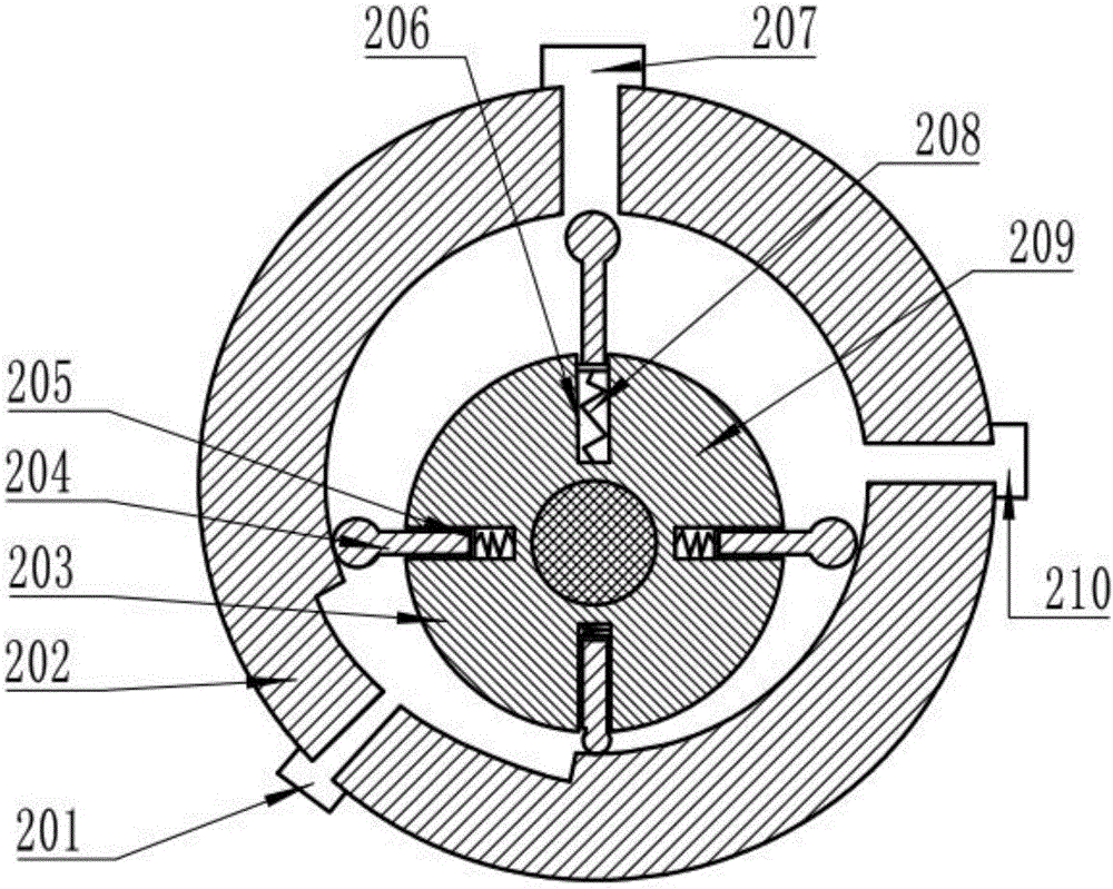
[0027] On the basis of Example 1, this embodiment discloses a preferred structure of a safe concrete pneumatic vibrating rod, such as image 3 As shown, the pneumatic device 12 is mainly composed of a pneumatic device air inlet 201, a body 202, a center wheel 203, a blade 204, a guide piece 205, a guide hole 206, a first exhaust port 207, a spring 208, a rotating shaft 209 and a first The body 202 is a circular hollow structure. The air inlet 201, the first exhaust port 207 and the second exhaust port 210 are arranged on the body 202; the first exhaust port 207 and The included angle between the second exhaust ports 210 is 90°, the opening angle of the air inlet 201 is 80°; the center wheel 203 is arranged inside the body 202, and the center of the center wheel 203 is connected to the rotating shaft 209; 209 is at a certain distance from the central axis of the body 202; there are four blades 204, guide pieces 205, guide holes 206 and springs 208; the four guide holes 206 are e...
Embodiment 3
[0030] On the basis of Examples 1 and 2, this embodiment discloses a preferred structure of a safe concrete pneumatic vibrator, such as figure 2 with 3 As shown, the vibrating rod exhaust port 2 is provided with a protective net. A protective net is set at the exhaust port to prevent debris from entering the equipment, affecting the normal operation of the equipment, and protecting the safety of the equipment.
[0031] Further, the working hard pipe 9 is a steel pipe. The steel pipe has high strength and low cost, which can effectively improve the economic benefits of the equipment.
[0032] Further, the center wheel 203 is provided with a breeding balance device. The blades will reciprocate during the rotation process, which affects the center of gravity of the equipment. With the addition of the counterweight device, the stability of the pneumatic device can be ensured.
[0033] Further, the top of the blade 204 is arc-shaped, and the arc surface of the top of the blade 204 is t...
PUM
 Abstract
Description
Claims
Application Information