Exhaust device

A technology for exhaust devices and jackets, which is applied in the automotive field and can solve problems such as difficult cleaning and easy sticking of rubber materials

Active Publication Date: 2017-02-22
CHENG SHIN RUBBER CHINA
View PDF5 Cites 3 Cited by
  • Summary
  • Abstract
  • Description
  • Claims
  • Application Information

AI Technical Summary

Problems solved by technology

[0004] The technical problem solved by the present invention is to provide an exhaust device. The exhaust device provided by this application can solve the problems that the rubber is easy to get stuck and difficult to clean.

Method used


Image

  • Exhaust device
  • Exhaust device
  • Exhaust device

Examples


Embodiment

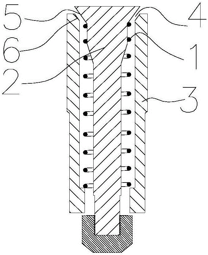
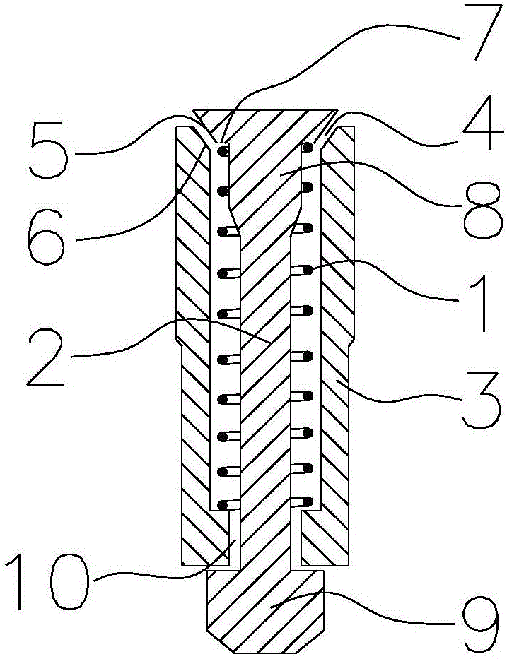
[0034] An exhaust device, comprising: an inner core, a spring and an outer jacket, the spring is located between the inner core and the outer jacket, and is placed outside the inner core, and a row is arranged between the outer jacket and the inner core. Air cavity;

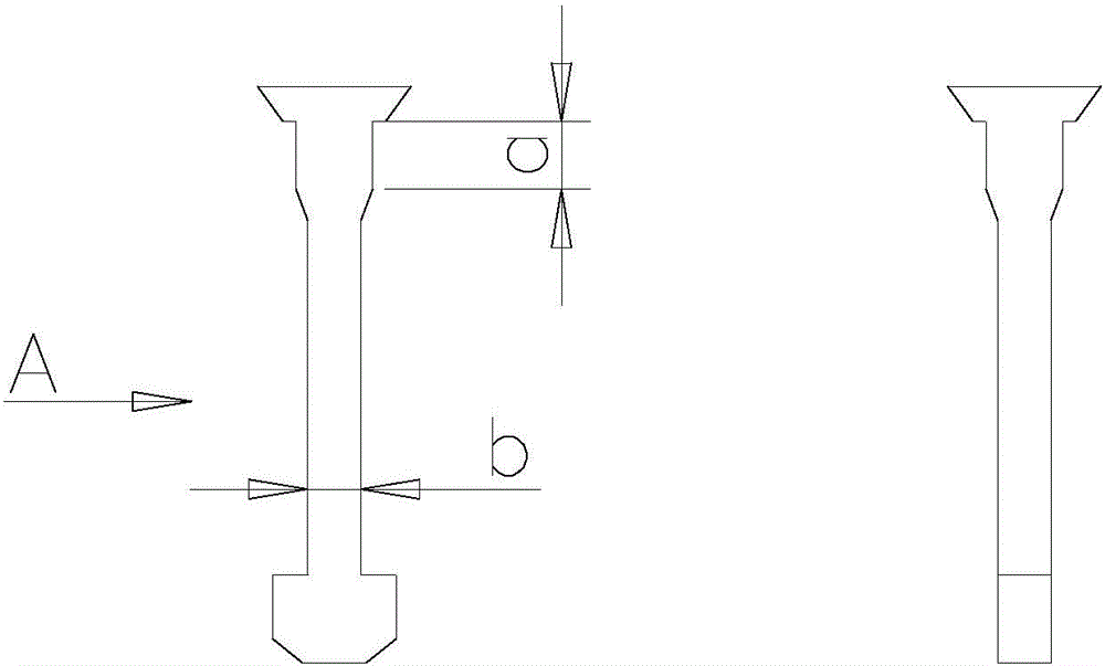
[0035] The inner core includes a core head, a core rod and a core tail, the core head is arranged at one end of the inner core close to the inner cavity of the tire molding mold, and the core head and the outer jacket are respectively provided with mutually matching core heads The sealing surface and the sealing surface of the jacket, the sealing surface of the core head and the top surface of the core head form an acute angle conical surface, so that the sealing surface of the core head and the sealing surface of the jacket form a seal when the raw tire is vulcanized; the sealing surface of the core head and the core There is a stepped surface between the rod sections, the width of the bottom surface of the core...


PUM

PropertyMeasurementUnit
lengthaaaaaaaaaa
heightaaaaaaaaaa
heightaaaaaaaaaa

Abstract

The invention provides an exhaust device. A spring is arranged between an inner core and an outer sleeve, and coats the inner core; an exhaust cavity is formed between the outer sleeve and the inner core; the inner core includes a core head, a core rod and a core tail; the diameter of the lower end surface of the core head is larger than the diameter of the upper end surface of the core rod; and the spring and the upper end of the core rod are in clearance fit. The exhaust device solves the problems of easy glue blockage and incapability of removing glue in a gap of the spring.

Description

technical field [0001] The invention relates to the technical field of automobiles, in particular to an exhaust device. Background technique [0002] The tire vulcanization mold is provided with air vents, so that the air between the raw tire and the mold can be discharged to the outside of the mold when the tire is vulcanized. Generally, the crown part mold is a straight through hole. When the air is discharged, the rubber on the raw tire will be discharged together due to the vulcanization pressure, and finally the rubber that needs to be removed will be left on the tire crown. [0003] In order to make the crown of the tire no longer produce hair rubber that needs to be removed, the existing spring exhaust device with an inner core solves this problem, such as figure 1 Exhaust device shown, figure 1 The exhaust device installs a spring 1 between the inner core 2 and the outer jacket 3, the inner core 2 includes a core head, a core rod and a core tail, and the core head ...

Claims


Application Information

Patent Timeline
Patent Type & Authority Applications(China)
IPC IPC(8): B29C33/10B29C35/00B29L30/00
CPCB29D30/0606B29D2030/0617
Inventor 罗才仁
Owner CHENG SHIN RUBBER CHINA
Why Eureka
Try Eureka