
Flatbed road wrecker with small dip angle
A technology for flatbed trucks and roads, which is applied in the field of small-inclination road obstacle-clearing flatbed trucks. It can solve the problems of difficult and safe loading of chassis vehicles, and achieve the effects of avoiding wheel scratches or damage, ensuring integrity and good stability
- Summary
- Abstract
- Description
- Claims
- Application Information
AI Technical Summary
Problems solved by technology
Method used
Image

Examples
Embodiment 1
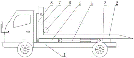
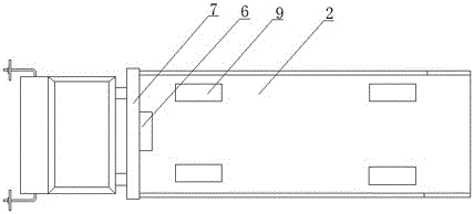
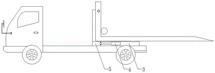
[0023] combined with Figure 1-5 As shown, a road wrecker with a small inclination angle includes a chassis 1, a carriage 2 installed on the chassis 1, and the end of the carriage 2 near the front is connected with a gantry 7, and the gantry 7 is close to the front One side of the flat frame 8 is hinged, and the other end of the flat frame 8 is fixedly connected to the first lifting frame 5 located under the carriage 2, and one end of the first lifting frame 5 is embedded in the second lifting frame 3 , a first hydraulic rod 4 is installed on the outside of the first lifting frame 5 and the second lifting frame 3, and the second lifting frame 3 is hinged to the chassis 1 through a second hydraulic rod 10; the gantry 7 is equipped with winch 6.
[0024] working principle:
[0025] Before explaining the working principle, some mechanical components designed to realize the principle are explained as follows: the articulation of all hydraulic rods in the present invention adopts...
Embodiment 2
[0029] combined with Figure 1-5 As shown, in order to further illustrate the present invention so that it has higher reliability and safety, on the basis of Embodiment 1, four lifting clips 9 are provided on the carriage 2 at the place where the wheels are parked.
[0030] In this embodiment, the lift clamp 9 is installed vertically to the surface of the carriage 2, and the upper end of the lift clamp 9 is bent at 90 degrees toward the center of the carriage 2 to form a pressing plate 91, and the lower surface of the pressing plate 91 is provided with There is a rubber layer 92, and a third hydraulic rod 93 is connected to the lower end of the lifting clamp 9.
[0031] In this embodiment, there are two first hydraulic rods 4 installed on both sides of the first lifting frame 5 and the second lifting frame 3 respectively.
[0032] In this embodiment, the number of the second hydraulic rods 10 is two, which are respectively hinged on both sides of the second lifting frame 3 . ...
PUM
 Abstract
Description
Claims
Application Information