Template detecting device with clamping and lifting mechanism
A template detection and template technology, applied in the direction of lifting devices, etc., can solve the problems of affecting health, reducing work efficiency, fatigue of observers, etc., and achieves the effects of convenient observation, improving work efficiency and reducing fatigue
- Summary
- Abstract
- Description
- Claims
- Application Information
AI Technical Summary
Problems solved by technology
Method used
Image

Examples
Embodiment Construction
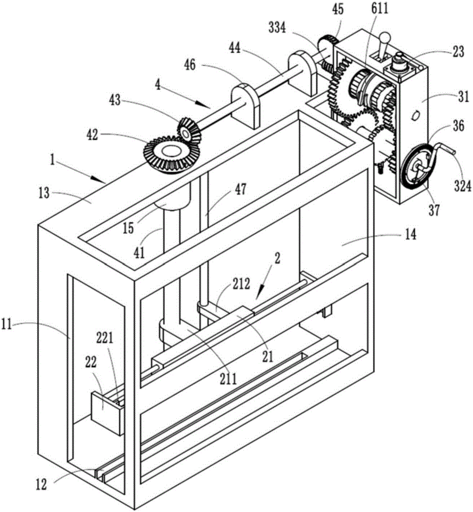
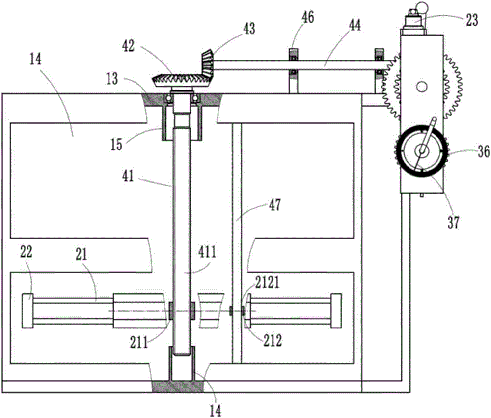
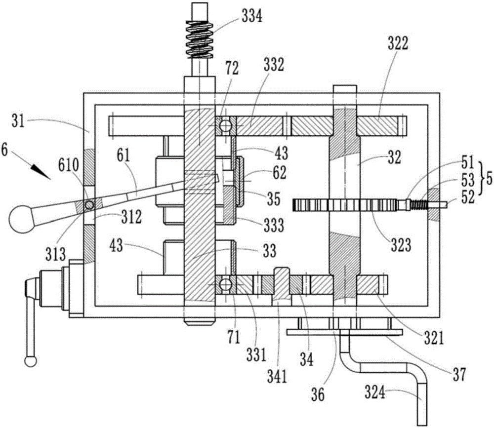
[0028] Examples, see e.g. Figure 1 to Figure 6 As shown, a template detection device provided with a clamping and lifting mechanism includes a detection frame 1, the left side wall of the detection frame 1 is provided with a feed port 11, and the bottom plate of the detection frame 1 is provided with a template slide. Road 12, the right side of the template slideway 12 is fixed with a blocking block, and the clamping mechanism 2 is provided directly above the template slideway 12, and the clamping mechanism 2 is movably connected with the transmission mechanism 4, and the turbine 45 of the transmission mechanism 4 is connected with the driving mechanism 3 The worm 334 is engaged, the base frame 31 of the driving mechanism 3 is fixed on the right side of the detection frame 1, the transmission mechanism 4 is installed on the rear part of the detection frame 1, and the front side of the detection frame 1 is equipped with an observation Mouth 14.
[0029] Furthermore, the clamp...
PUM
 Abstract
Description
Claims
Application Information
 - R&D
- Intellectual Property
- Life Sciences
- Materials
- Tech Scout
- Unparalleled Data Quality
- Higher Quality Content
- 60% Fewer Hallucinations
Browse by: Latest US Patents, China's latest patents, Technical Efficacy Thesaurus, Application Domain, Technology Topic, Popular Technical Reports.
© 2025 PatSnap. All rights reserved.Legal|Privacy policy|Modern Slavery Act Transparency Statement|Sitemap|About US| Contact US: help@patsnap.com