Floor fastener capable of preventing inflation and shrinkage

A floor lock and lock technology, which is applied in the direction of floors, buildings, building structures, etc., can solve problems such as falling off, poor stability, and high cost, and achieve thermal expansion and contraction resistance, strong tensile resistance, and shrinkage resistance powerful effect

Inactive Publication Date: 2017-02-22
ANHUI HANHUA BUILDING MATERIALS TECH
View PDF8 Cites 2 Cited by
  • Summary
  • Abstract
  • Description
  • Claims
  • Application Information

AI Technical Summary

Problems solved by technology

[0004] The structure of the floor locks in the prior art is similar, and both ends are provided with male and female falcons for mutual cooperation and connection, but there are some problems in the existing locks, especially in the case of using geothermal heat, the floor The phenomenon of thermal expansion and contraction is more serious, and the gap between the floors is large, which will cause the floor to shake easily in summer, and the stability is poor, while the gap between the floors is small, which will cause the floor to be squeezed and deformed under the conditions of thermal expansion and contraction in winter In addition, cuttings are generally provided at the joints of the male falcon and the female falcon to combine them, so that the corners have the effect of preventing stretching, and the use of cuttings will inevitably lead to complicated processing of the floor , the cost is also high, and the plastic shrinkage is more serious for the plastic bottom plate. The existing floor locks may cause the locks to bite, shake or even fall off when shrinking.

Method used


Image

  • Floor fastener capable of preventing inflation and shrinkage

Examples


Embodiment Construction

[0023] In order to make the technical means realized by the present invention, the novel features created, the purpose achieved and the effects achieved clearly understood, the present invention will be further elaborated below in conjunction with specific illustrations.

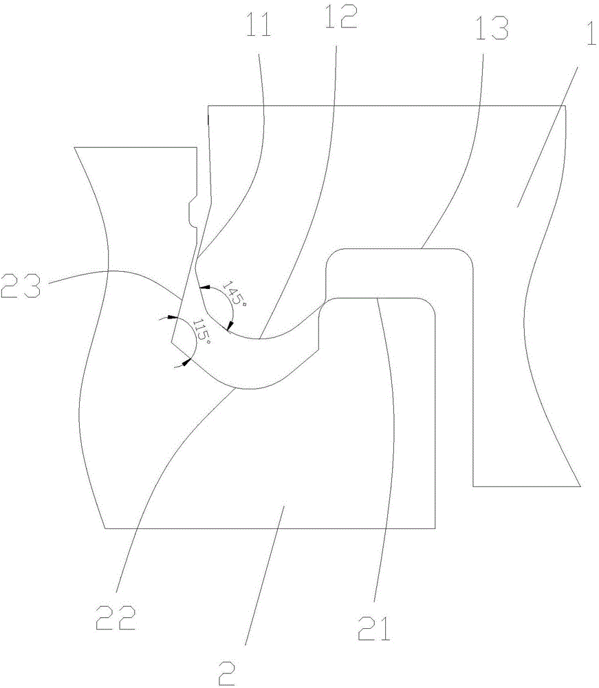
[0024] Such as figure 1 As shown, a floor lock that prevents expansion and contraction includes a male falcon 1 and a female falcon 2; the lower side of the end of the male falcon 1 is provided with a first protrusion 11, and the lower side of the end of the male falcon 1 is next to the first protrusion. The inner side of the part 11 is provided with a second protruding part 12, and the lower side of the end of the male falcon 1 is provided with a groove part 13 next to the inner side of the second protruding part 12; The upper side of the end of the falcon 2 is provided with a first groove portion 22 next to the inside of the raised portion 21, and the upper side of the end of the female falcon 2 is provide...


PUM


Abstract

The invention provides a floor fastener capable of preventing inflation and shrinkage and relates to the technical field of floors. The fastener comprises a male fastener and a female fastener; a first boss is arranged at the lower side of the end part of the male fastener, a second boss part is arranged at the inner side, which is close to the first boss par, of the lower side of the end part of the male fastener, and a groove part is arranged at the inner side, which is close to the second boss part, of the lower side of the end part of the male fastener; the upper side of the end part of the female fastener is provided with a boss part, a first boss part is arranged at the inner side, which is close to the boss part, of the upper side of the end part of the female fastener, and a second groove part is arranged at the inner side, which is close to of the first groove part, of the upper side of the end part of the female fastener. The included angle between the first boss part and the second boss part is 140 degrees to 150 degrees, and the included angle between the first groove part and the second groove part is 110 degrees to 120 degrees. When the fastener is connected with the floor, the first boss part of the male fastener is matched with the second groove part of the female fastener of the female fastener, the second boss part of the male fastener is matched with the first groove part of the female fastener, and the groove part of the male flacon is matched with the boss part of the female fastener. The floor fastener capable of preventing inflation and shrinkage prevents deformation due to thermal expansion and contraction, and is strong is tensile ability, convenient to install, low in production coat and simple in technology.

Description

[0001] Technical field: [0002] The invention relates to the field of floor technology, in particular to a floor lock that prevents expansion and contraction. [0003] Background technique: [0004] The structure of the floor locks in the prior art is similar, and both ends are provided with male and female falcons for mutual cooperation and connection, but there are some problems in the existing locks, especially in the case of using geothermal heat, the floor The phenomenon of thermal expansion and contraction is more serious, and the gap between the floors is large, which will cause the floor to shake easily in summer, and the stability is poor, while the gap between the floors is small, which will cause the floor to be squeezed and deformed under the conditions of thermal expansion and contraction in winter In addition, cuttings are generally provided at the joints of the male falcon and the female falcon to combine them, so that the corners have the effect of preventing s...

Claims


Application Information

Patent Timeline
Patent Type & Authority Applications(China)
IPC IPC(8): E04F15/02
CPCE04F15/02038E04F2201/03
Inventor 李小林
Owner ANHUI HANHUA BUILDING MATERIALS TECH
Why Eureka
Try Eureka