A system that drives a liquid working medium to do work by vapor pressure

A technology of vapor pressure and working medium, which is applied in the direction of steam engine devices, machines/engines, mechanical equipment, etc., can solve the problems of low thermal efficiency, low-temperature heat energy discharge, etc., and achieve the effect of improving thermal efficiency

Active Publication Date: 2018-11-02
镇江市恒利低温技术有限公司
View PDF4 Cites 0 Cited by
  • Summary
  • Abstract
  • Description
  • Claims
  • Application Information

AI Technical Summary

Problems solved by technology

As a result, a large amount of low-temperature heat energy may be discharged to the environment during the condensation process, and since the latent heat of vaporization of the working fluid is much higher than the specific heat capacity, the thermal efficiency of this method is low

Method used


Image

  • A system that drives a liquid working medium to do work by vapor pressure
  • A system that drives a liquid working medium to do work by vapor pressure
  • A system that drives a liquid working medium to do work by vapor pressure

Examples


specific Embodiment approach 1

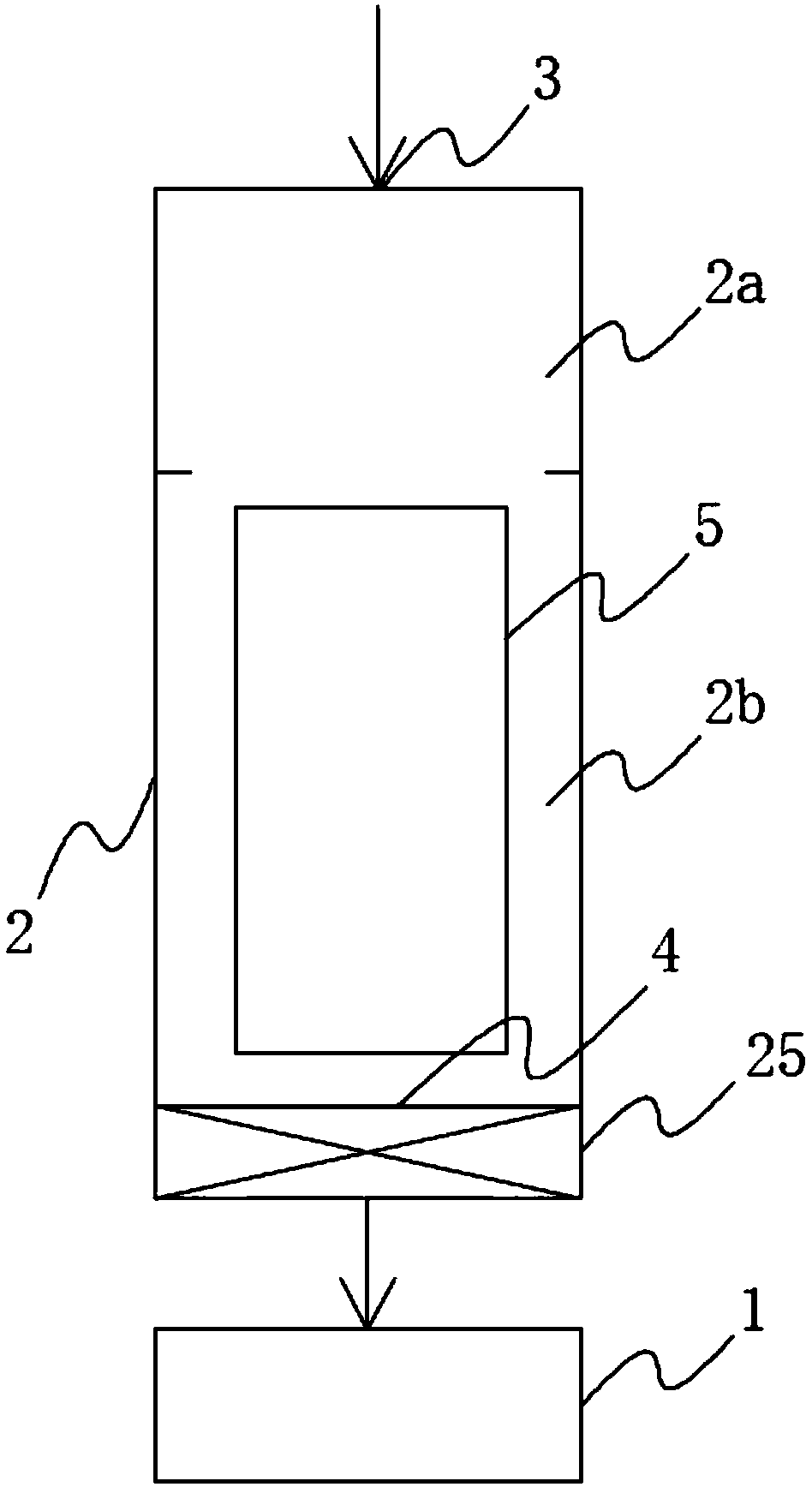
[0028] like figure 1 As shown in , a system for driving a liquid working medium to do work by vapor pressure according to the present invention includes a work device 1 and a diversion channel 2, and the diversion channel 2 includes a steam chamber 2a and a liquid chamber communicated with each other 2b, the steam chamber 2a is located above the liquid chamber 2b; a working medium inlet 3 communicating with the steam chamber 2a and a working medium outlet 4 communicating with the liquid chamber 2b are provided on the diversion channel 2; the working device 1 and the working medium The medium outlet 4 is connected; a cooling device 5 for cooling the working medium is arranged between the working medium inlet 3 and the working medium outlet 4 in the diversion channel 2 . Wherein, the work device 1 can be a power generating device or a mechanical power device, and the power for doing work is provided by the liquid working fluid discharged from the working medium outlet 4 on the f...

specific Embodiment approach 2

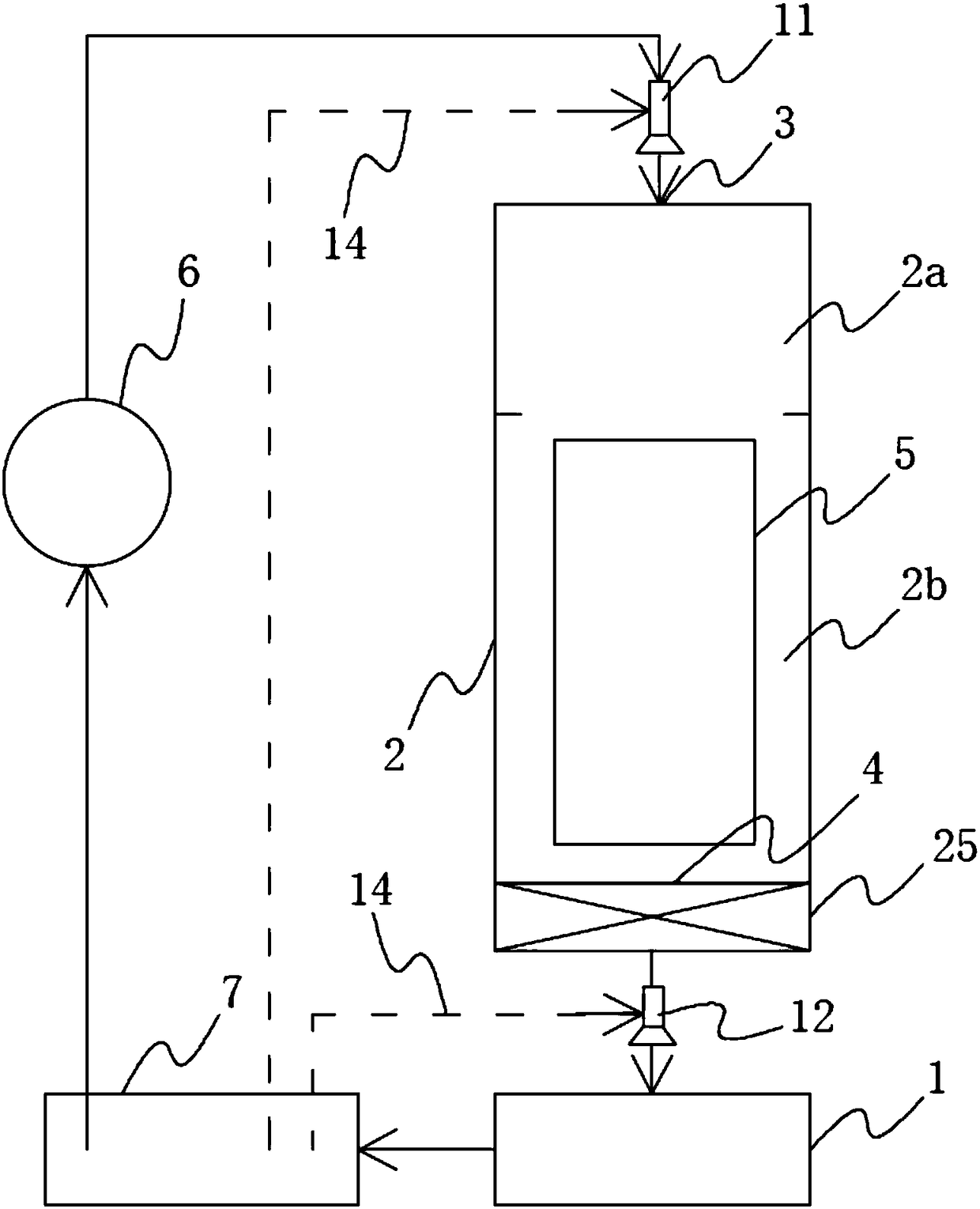
[0032] Refer to attached figure 2 As shown in , on the basis of the above specific embodiment 1, the system also includes a heat source 6 and a working medium pool 7, wherein the working medium pool 7 is connected with the work device 1 to collect the liquid working medium after passing through the work device 1 ; The heat source 6 is connected to the working fluid inlet 3 on the working fluid pool 7 and the diversion channel 2 respectively through pipelines. In this way, by introducing the corresponding heat source 6 on the basis of the specific embodiment 1, the liquid working medium collected in the working medium pool 7 after passing through the work device 1 can be directly reheated through the heat source 6 to form high-temperature and high-pressure steam Or the high-temperature liquid is added into the diversion channel 2 again through the working medium inlet 3, so as to realize the circulation of the system. The heat source 6 can be a device that heats the liquid wo...

specific Embodiment approach 3

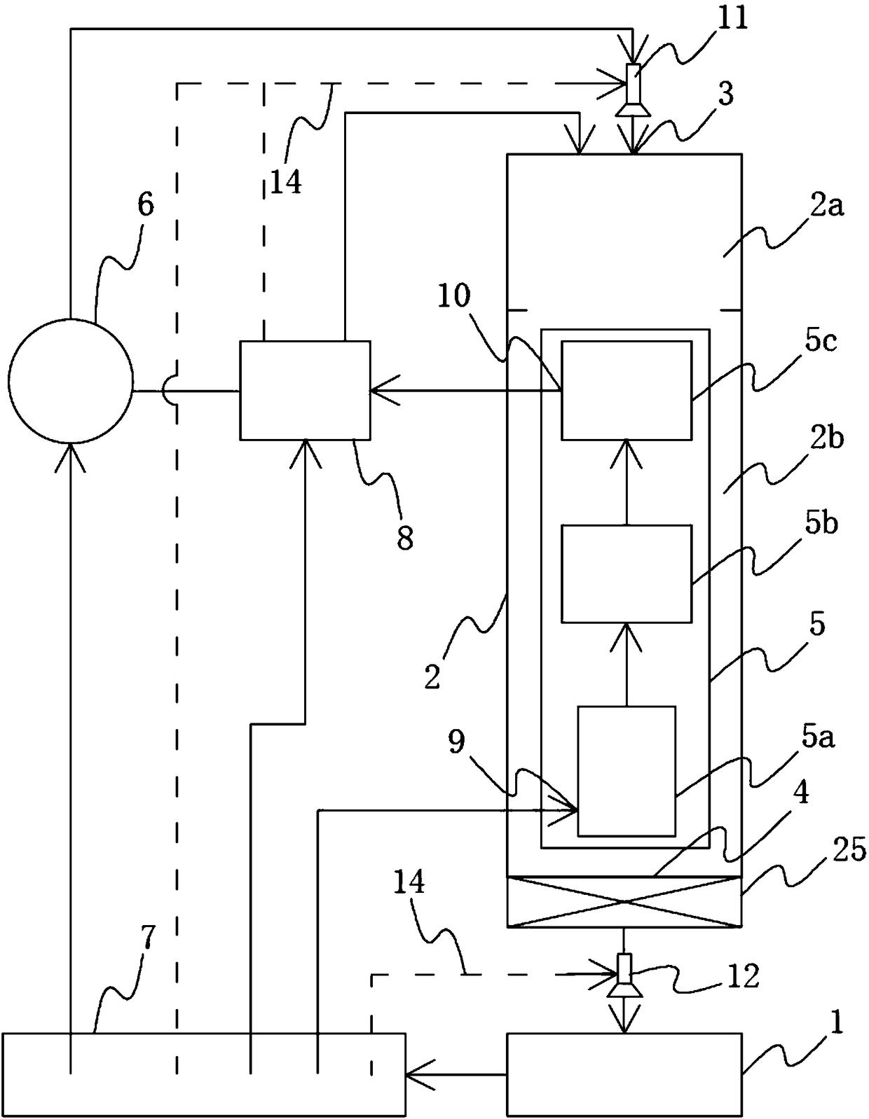
[0033] In the above-mentioned specific embodiment 1 and specific embodiment 2, the function of the cooling device 5 is to cool down the high-temperature working fluid in the diversion channel 2 . In order to further recycle the energy released in the cooling process to improve energy utilization; refer to the attached image 3 As shown in , on the basis of the above-mentioned specific embodiment 2, a heating container 8 is further provided; the cooling device 5 includes at least one heat exchanger, and the cooling device 5 is provided with heat exchangers respectively communicated with the heat exchanger An inlet 9 and a heat exchange outlet 10, the heat exchange inlet 9 is connected to the working medium pool 7 through a pipeline; the heating container 8 is connected to the working medium pool 7 and the heat exchange outlet 10 on the cooling device 5 through a pipeline; The heat source 6 is connected to a heating container 8 . At this time, the low-temperature liquid working...


PUM


Abstract

The invention discloses a system for driving a liquid working medium to act through steam pressure belong to the technical field of steam turbines, and provides a new system for driving the liquid working medium to act with the steam pressure as power to effectively improve the heat efficiency. The system comprises an acting device, and further comprises a guide channel; the guide channel includes a steam cavity and a liquid cavity communicated with each other; the steam cavity is positioned above the liquid cavity; the guide channel is provided with a working medium inlet communicated with the steam cavity, and a working medium outlet communicated with the liquid cavity; the acting device is connected with the working medium outlet; and a cooling device for cooling the working medium is arranged between the working medium inlet and the working medium outlet in the guide channel. As the process of converting high-temperature and high-pressure steam from a gas state to liquid is before acting of the high-temperature and high-pressure steam, the vaporization latent heat of the gas-state steam working medium is not discharged in the environment, the total heat efficiency can be greatly improved, and the acting device is effectively protected.

Description

technical field [0001] The invention relates to the technical field of steam engines, in particular to a system for driving a liquid working medium to do work through vapor pressure. Background technique [0002] So far, most of the devices for doing work or generating electricity have achieved the purpose of doing work or generating electricity by forming high-temperature and high-pressure gas, and then expanding the high-temperature and high-pressure gas. There are generally two ways to form high-temperature and high-pressure gas: one is to make combustible fuel react with oxygen in the air, and directly form high-temperature and high-pressure gas through combustion; the other is to heat the liquid working medium by burning the fuel, such as Water evaporates the liquid working medium to form high-temperature and high-pressure gas, such as internal combustion engines, gas turbines, steam engines, etc. [0003] Among them, by heating the liquid working medium, the liquid wo...

Claims


Application Information

Patent Timeline
Patent Type & Authority Patents(China)
IPC IPC(8): F01K25/02
CPCF01K25/02
Inventor 郑成勋
Owner 镇江市恒利低温技术有限公司
Why Eureka
Try Eureka