Hot gas turbine

A hot gas and turbine technology, used in gas turbine devices, mechanical equipment, engine components, etc., can solve the problems of difficult to further improve thermal efficiency, high material cost, high construction cost, and achieve the effect of reduced flow resistance, reasonable structural design, and reduced cost.

Inactive Publication Date: 2010-06-30
姜文岐
View PDF6 Cites 0 Cited by
  • Summary
  • Abstract
  • Description
  • Claims
  • Application Information

AI Technical Summary

Problems solved by technology

[0003] There are two major problems in existing gas turbines: 1. The cost is extremely high; 2. It is difficult to further improve the thermal efficiency. The cost of materials is extremely high, and complex blade cooling measures have to be taken, and the performance of the material is close to the limit; the reason why it is difficult to further improve the thermal efficiency is that the existing method of improving thermal efficiency is to increase the air pressure of the compressor and increase the temperature of the gas, which is limited by the performance of the material , has no potential to be tapped

Method used


Image

  • Hot gas turbine
  • Hot gas turbine
  • Hot gas turbine

Examples


Embodiment 1

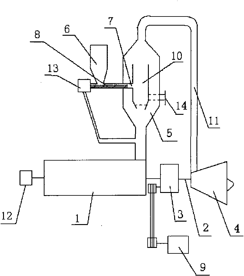
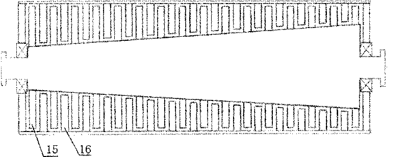
[0018] A kind of heat turbine of the present embodiment refers to the appended figure 1 , 3 , including a compressor 1 connected to the driving device 12 and densely covered with rotor blades 15 and stator blades 16 inside, the output end of the compressor 1 communicates with the cold air channel 5 with a fuel combustion chamber 10 inside, and the combustion chamber 10 is A fuel delivery device is provided, the cold air channel 5 is connected with the hot gas turbine 4 through the gas and cold air mixed hot gas pipeline 11, and a speed reducer 3 is installed between the heat gas turbine 4 and the compressor 1, and the speed reducer 3 is connected with a load 9; The machine 3 is connected with the hot gas turbine 4 and the compressor 1 through the transmission shaft 2; the fuel delivery device includes a power transmission device 13 connected to the output end of the compressor 1, and the power transmission device 13 drives the fuel delivery device 8 connected thereto to work, ...

Embodiment 2

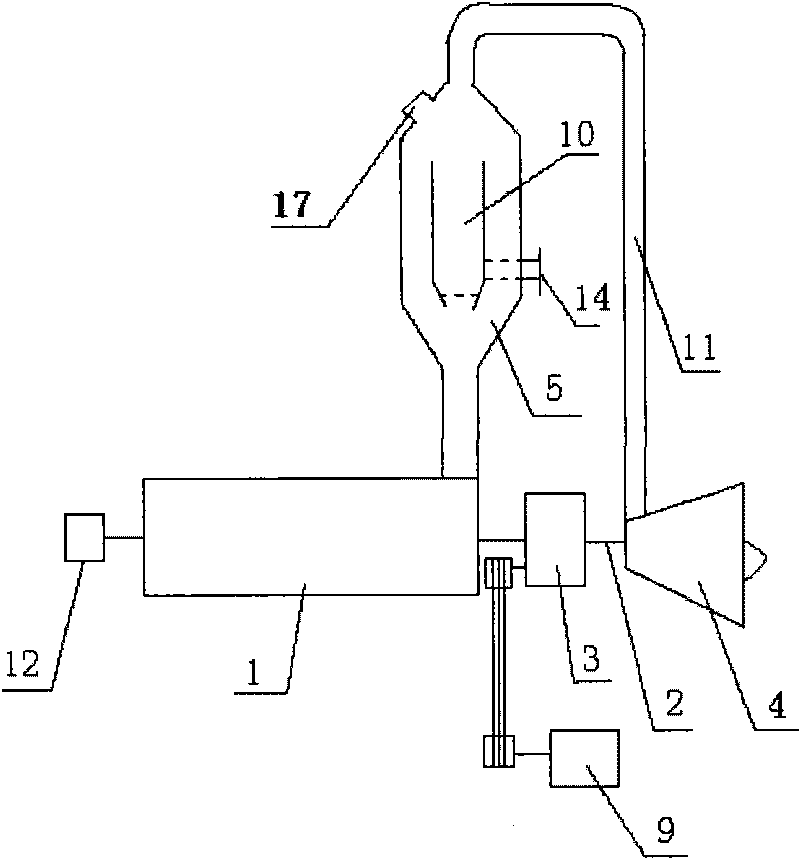
[0020] The difference between this embodiment and Embodiment 1 is that the fuel delivery device is the feed port 17 provided on the cold air channel 5 .

[0021] Working principle: the driving device 12 drives the compressor 1 to work, the compressed air enters the cold air passage 5, and the fuel combustion chamber 10 is arranged in the cold air passage 5, and the fuel is sent into the combustion chamber 10 through the fuel delivery device, and the fuel is in the combustion chamber After combustion, high-heat gas will be produced, and the gas will be mixed with the compressed cold air to reduce the temperature of the gas, and the gas and cold air will be sprayed to the hot gas turbine 4 through the gas and cold air mixed hot gas pipeline 11, driving the hot gas turbine 4 to run at a high speed. The temperature of the gas working medium is lower, so that the service life of the blades of the hot gas turbine is increased, and the cost of blade materials is reduced. The turbine o...


PUM


Abstract

The invention relates to a hot gas turbine, which belongs to the technical field of hot gas turbine structures. The hot gas turbine comprises a gas compressor, wherein the gas compressor is connected with driving equipment; rotor vanes and stator vanes are densely distributed in the gas compressor; the output end of the gas compressor is communicated with a cold air channel in which a fuel combustion chamber is arranged; the combustion chamber is provided with a fuel delivery device; the cold air channel is communicated with the hot gas turbine through a fuel gas and cold air mixed hot-gas pipeline; and a speed reducer is arranged between the hot gas turbine and the gas compressor and is connected with a load. The hot gas turbine has the characteristics of rational structural design, low cost, high heat efficiency and durability.

Description

technical field [0001] The invention relates to a heat turbine, which belongs to the technical field of heat turbine structure. Background technique [0002] At present, the working principle of the traditional gas turbine is: the inhaled air is compressed to a pressure of several kilograms or more than 20 kilograms per square centimeter by the compressor, enters the combustion chamber and is mixed with fuel for combustion, and high-temperature gas is sprayed to the gas turbine to make the gas turbine run at high speed Power is generated, and then the gas turbine drives the compressor to work, and the transmission mechanism outputs power to the outside. [0003] There are two major problems in existing gas turbines: 1. The cost is extremely high; 2. It is difficult to further improve the thermal efficiency. The cost of materials is extremely high, and complex blade cooling measures have to be taken, and the performance of the material is close to the limit; the reason why i...

Claims


Application Information

Patent Timeline
Patent Type & Authority Applications(China)
IPC IPC(8): F02C7/36F02C3/14F02C7/22F02C7/18
Inventor 姜文岐
Owner 姜文岐
Why Eureka
Try Eureka