S-shaped bent shrinking-expanding spray pipe structure

A tube structure and nozzle technology, applied in the directions of jet propulsion, machine/engine, etc., can solve the problem that the retractable engine tail nozzle cannot meet the coverage of sub-, cross- and supersonic flight of fighters.

Inactive Publication Date: 2017-02-22
NORTHWESTERN POLYTECHNICAL UNIV
View PDF5 Cites 13 Cited by
  • Summary
  • Abstract
  • Description
  • Claims
  • Application Information

AI Technical Summary

Problems solved by technology

[0004] The main purpose of the present invention is to provide a kind of S-curved retraction-spreading nozzle structure, to at least solve the proble...

Method used


Image

  • S-shaped bent shrinking-expanding spray pipe structure
  • S-shaped bent shrinking-expanding spray pipe structure

Examples


Embodiment Construction

[0022] In order to enable those skilled in the art to better understand the solutions of the present invention, the following will clearly and completely describe the technical solutions in the embodiments of the present invention in conjunction with the drawings in the embodiments of the present invention. Obviously, the described embodiments are only It is an embodiment of a part of the present invention, but not all embodiments. Based on the embodiments of the present invention, all other embodiments obtained by persons of ordinary skill in the art without making creative efforts shall fall within the protection scope of the present invention.

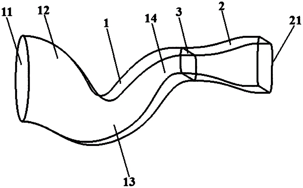
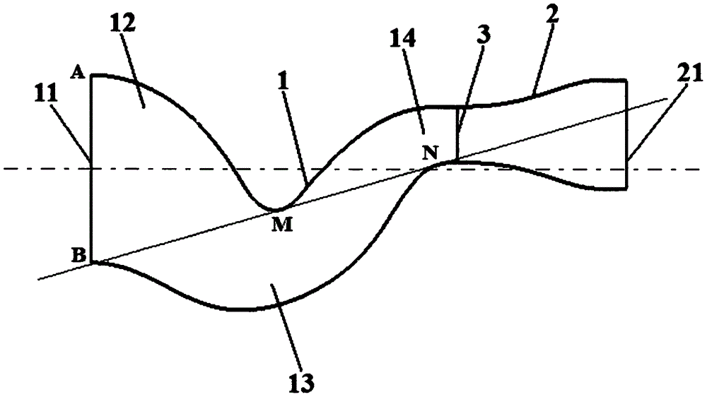
[0023] According to an S-curved diversion-diffusion pipe structure according to an embodiment of the present invention, such as figure 1 As shown, it includes: a contraction section 1 and an expansion section 2. The contraction section 1 has an air inlet 11 connected to the high-temperature turbine outlet of the engine. The expansio...


PUM


Abstract

The invention discloses an S-shaped bent shrinking-expanding spray pipe structure which comprises a shrinking section and an expanding section; the shrinking section is equipped with a gas inlet which is connected with a high-temperature turbine outlet of an engine; the expanding section is connected to the tail part of the shrinking section and is equipped with a gas outlet; and a spray pipe throat is formed on a transition part of the shrinking section and the expanding section. According to the S-shaped bent shrinking-expanding spray pipe structure which adopts the technical scheme, gas flow from the high-temperature turbine outlet of the engine is expanded and accelerated during shrinking and expanding, and is accelerated to sound speed at the spray pipe throat; and the gas flow which reaches sound speed is further accelerated to ultrasonic sound speed at the expanding section after passing through the spray pipe throat. The S-shaped bent shrinking-expanding spray pipe structure disclosed by the invention solves the problem that a shrinking type engine tail spray pipe adopted by a warplane in the prior art cannot meet the needs of covering infrasound speed flight, transonic sped flight and ultrasonic sound speed flight of the warplane.

Description

technical field [0001] The invention relates to the field of aero-engines, in particular to an S-bend diverter-spray nozzle structure. Background technique [0002] With the rapid development of advanced infrared guided missiles, airborne infrared search and track systems and radar guidance technology, modern fighters have higher and higher requirements for infrared stealth technology and radar stealth technology. The research shows that the S-bend nozzle has become the research focus of low detectability technology because of its obvious advantages as follows. On the one hand, the S-curved surface can effectively shield internal high-temperature components such as turbine guides and afterburner flame stabilizers, significantly reduce their infrared radiation, and enhance the radar stealth characteristics of the exhaust system; on the other hand, the use of S The curved channel makes the incident electromagnetic wave repeatedly refracted and consumed in the S-curved channel...

Claims


Application Information

Patent Timeline
IPC IPC(8): F02K1/06
CPCF02K1/06
Inventor 孙啸林王占学周莉史经纬张明阳程稳
Owner NORTHWESTERN POLYTECHNICAL UNIV
Why Eureka
Try Eureka