
A plunger pair structure for ultra-high pressure axial swash plate plunger pump

A swash plate plunger pump and plunger pair technology, which is applied to the components of the pumping device for elastic fluids, pump components, variable displacement pump components, etc. , reduce the volume efficiency of the pump, etc., to achieve the effect of simple structure and convenient use

Active Publication Date: 2019-02-22
CHINA SHIP SCIENTIFIC RESEARCH CENTER (THE 702 INSTITUTE OF CHINA SHIPBUILDING INDUSTRY CORPORATION)
View PDF7 Cites 0 Cited by
  • Summary
  • Abstract
  • Description
  • Claims
  • Application Information

AI Technical Summary

Problems solved by technology

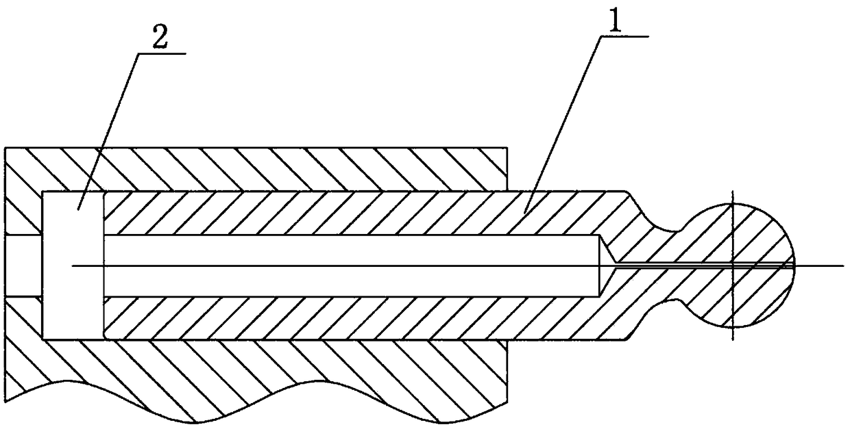
The plunger pair is the core component of the axial piston pump. The existing structure of the plunger pair is as follows: figure 1 As shown, including the plunger 1 and the cylinder hole 2, when the plunger 1 compresses the working medium in the cylinder hole 2, since the swash plate has a certain inclination angle, there is a normal force between the plunger 1 and the cylinder hole 2. When the outer surface of the plunger and the inner surface of the cylinder bore form a pair of friction pairs under the normal pressure, this will cause the wear of the plunger and the cylinder bore, reduce the volumetric efficiency of the pump, and restrict the life of the pump
The normal pressure between the plunger and the cylinder bore is positively correlated with the working pressure of the axial piston pump. Therefore, for an ultra-high pressure axial piston pump, if the traditional plunger pair structure is adopted, the wear rate of the plunger and the cylinder bore will be significantly higher than ordinary axial piston pumps, which is extremely detrimental to the reliability and life of the pump

Method used


Image

  • A plunger pair structure for ultra-high pressure axial swash plate plunger pump
  • A plunger pair structure for ultra-high pressure axial swash plate plunger pump
  • A plunger pair structure for ultra-high pressure axial swash plate plunger pump

Examples


Embodiment Construction

[0020] Specific embodiments of the present invention will be described below.

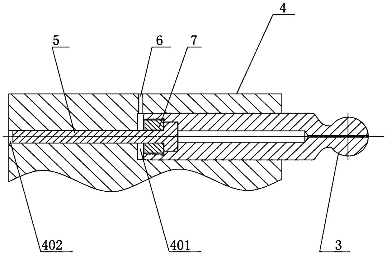
[0021] Such as figure 2 As shown, a plunger pair structure for an ultra-high pressure axial plunger pump includes a cylinder 4, a first plunger hole 401 for installing the first plunger 3 and a first plunger hole 401 for installing the first plunger 3 are opened in the cylinder 4 respectively. The second plunger hole 402 of the second plunger 5, the above-mentioned first plunger hole 401 communicates with the second plunger hole 402 to form a stepped hole, and the first plunger 3 extends into one end of the first plunger hole 401 by pressing The nut 7 cooperates with the end of the second plunger 5 extending into the first plunger hole 401 . On the cylinder body 4, also offer the small hole 6 that communicates with the first plunger hole 401, the central axis of the small hole 6 is perpendicular to the central axis of the first plunger hole 401, and the small hole 6 is not connected with the firs...


PUM


Abstract

The invention relates to a plunger pair structure used for an ultra-high-pressure axial plunger pump. The plunger pair structure comprises a cylinder. A first plunger hole used for installing a first plunger and a second plunger hole used for installing a second plunger are formed in the cylinder. The end, stretching in the first plunger hole, of the first plunger is matched with the end, stretching in the first plunger hole, of the second plunger through a pressing nut. The plunger pair structure is simple and convenient to use, and when the second plunger compresses working media in the second plunger hole, the second plunger is not affected by the normal pressure action or hardly affected by the normal pressure action. The normal pressure, acting on the spherical end of the first plunger, of an oblique disc is balanced through the normal pressure acting on the first plunger through the first plunger hole. Due to the fact that the diameter of the first plunger is smaller than that of a small plunger, the normal pressure between the first plunger and the first plunger hole can be reduced to the allowed level, and it is guaranteed that the abrasion rate of a first plunger pair and the abrasion rate of a second plunger pair are controlled at the normal level.

Description

technical field [0001] The invention relates to the technical field of fluid transmission and hydraulic transmission, in particular to a plunger pair structure for an ultra-high pressure axial plunger pump. Background technique [0002] Many applications in the field of engineering hydraulics require that the maximum working pressure of the hydraulic pump can reach the ultra-high pressure level, and the axial piston pump is an ideal structure for the hydraulic pump to achieve ultra-high pressure output. The life of the axial piston pump mainly depends on three key frictions The life of the pair, the plunger / cylinder bore friction pair is one of the three key friction pairs of the axial piston pump. The plunger pair is the core component of the axial piston pump. The existing structure of the plunger pair is as follows: figure 1 As shown, including the plunger 1 and the cylinder hole 2, when the plunger 1 compresses the working medium in the cylinder hole 2, since the swash ...

Claims


Application Information

Patent Timeline
Patent Type & Authority Patents(China)
IPC IPC(8): F04B53/14
CPCF04B53/14
Inventor 刘浩胡震叶聪汤国伟张小献
Owner CHINA SHIP SCIENTIFIC RESEARCH CENTER (THE 702 INSTITUTE OF CHINA SHIPBUILDING INDUSTRY CORPORATION)
Learn More