Transitional flange used between motor and fan

A transitional flange and fan technology, which is applied to parts of pumping devices for elastic fluids, machines/engines, mechanical equipment, etc., can solve the problems of resource occupation and different sizes of fan flanges, and reduce spare parts, cost saving effect

Inactive Publication Date: 2017-02-22
天津市新宇彩板有限公司
View PDF0 Cites 0 Cited by
  • Summary
  • Abstract
  • Description
  • Claims
  • Application Information

AI Technical Summary

Problems solved by technology

[0002] In the rolling mill workshop, the power of the left and right coilers needs to be provided by two high-power motors. The high-power motors generate a lot of heat during operation, and fans are required to provide cooling. Due to the different models of high-power motors, the flange sizes of the required fans are different. , when it comes to spare parts, it is necessary to prepare multiple fans of different models, resulting in resource occupation

Method used


Image

  • Transitional flange used between motor and fan
  • Transitional flange used between motor and fan

Examples


Embodiment Construction

[0011] The present invention will be further described in detail below in conjunction with the accompanying drawings and through specific embodiments. The following embodiments are only descriptive, not restrictive, and cannot limit the protection scope of the present invention.

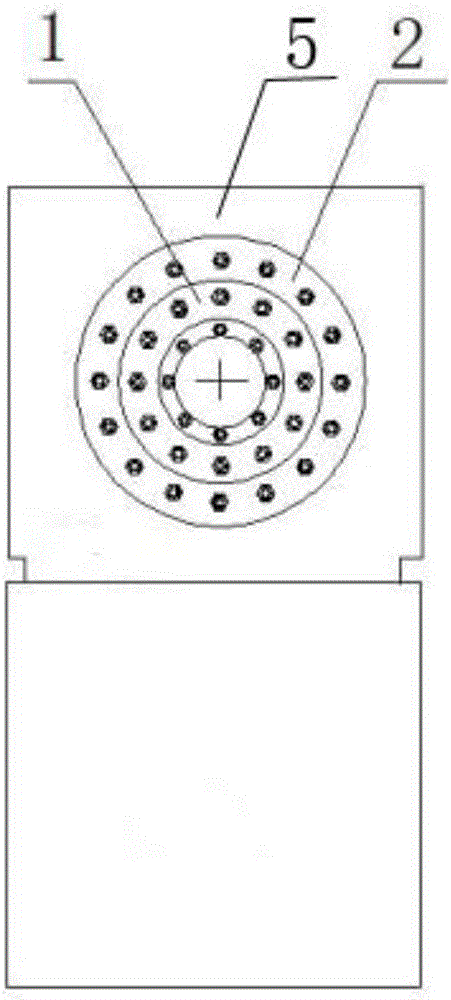
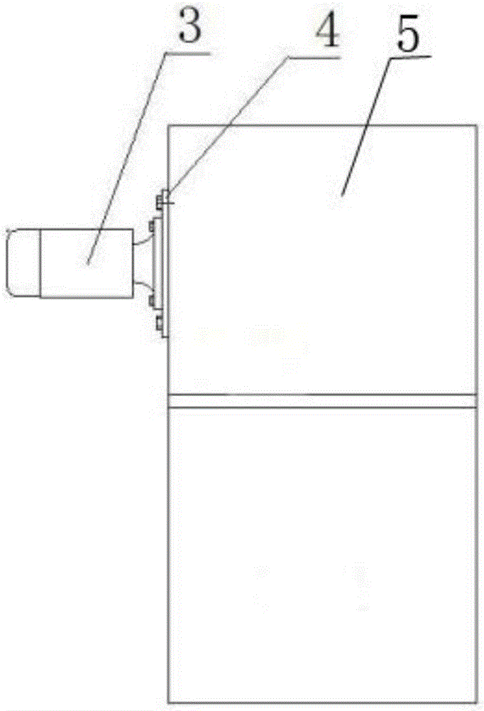
[0012] A transition flange used between the motor and the fan. The transition flange 4 is installed on the fan box body 5, and the motor 3 is installed through the shaft on the transition flange. The transition flange is divided into an inner ring 1 and an outer ring 2. There are screw holes evenly distributed on the circumference of the inner ring. The screw holes are aligned with the screw holes set on the fan box body. The screw hole positions on the outer ring of the transition flange are based on different standards of motor flange Correspondingly, annular screw holes with multiple radii are provided. When replacing the motor, you only need to remove the screws on the motor flange to replace it,...


PUM


Abstract

The invention relates to a transitional flange used between a motor and a fan. The transitional flange is mounted on a fan box body; a motor is mounted on the transitional flange through a shaft; the transitional flange is divided into an inner ring and an outer ring; screw holes are formed in the inner ring circumferentially at the same interval; and a plurality of annular screw holes with different radius are formed in the outer ring of the transitional flange correspondingly according to the hole positions of the motor flange screw holes with different modes. According to the transitional flange provided by the invention, when the motor is replaced, the motor can be replaced only by disassembling screws of the motor flange and without replacing the transitional flange; and when spare parts are prepared, the spare parts can be effectively reduced and the cost is reduced.

Description

technical field [0001] The invention belongs to the field of color steel plate manufacturing equipment, in particular to a transition flange used between a motor and a fan. Background technique [0002] In the rolling mill workshop, the power of the left and right coilers needs to be provided by two high-power motors. The high-power motors generate a lot of heat during operation, and fans are required to provide cooling. Due to the different models of high-power motors, the flange sizes of the required fans are different. , when it comes to spare parts, it is necessary to prepare multiple fans of different types, resulting in resource occupation. Contents of the invention [0003] The purpose of the present invention is to overcome the disadvantages of the prior art, and provide an easy-to-replace, stable-assemble transition flange used between the motor and the fan. [0004] The present invention solves its technical problem and realizes by taking the following technical...

Claims


Application Information

Patent Timeline
Patent Type & Authority Applications(China)
IPC IPC(8): F04D25/08F04D29/00F04D29/60
CPCF04D25/082F04D29/002F04D29/601
Inventor 郭振刚
Owner 天津市新宇彩板有限公司
Why Eureka
Try Eureka