Punch rivet

A punching riveting and riveting rod technology, which is applied in the direction of rivets, threaded fasteners, connecting components, etc., can solve the problem that the vibration-assisted punching riveting method is not the best structure, etc., so as to improve the cutting process, stabilize the pressing process, and avoid swing effect

Inactive Publication Date: 2017-02-22
ROBERT BOSCH GMBH
View PDF5 Cites 2 Cited by
  • Summary
  • Abstract
  • Description
  • Claims
  • Application Information

AI Technical Summary

Problems solved by technology

However, it has been shown that conventional rivet geometries are not optimally configured for vibration-assisted punching methods

Method used


Image

  • Punch rivet
  • Punch rivet
  • Punch rivet

Examples


Embodiment Construction

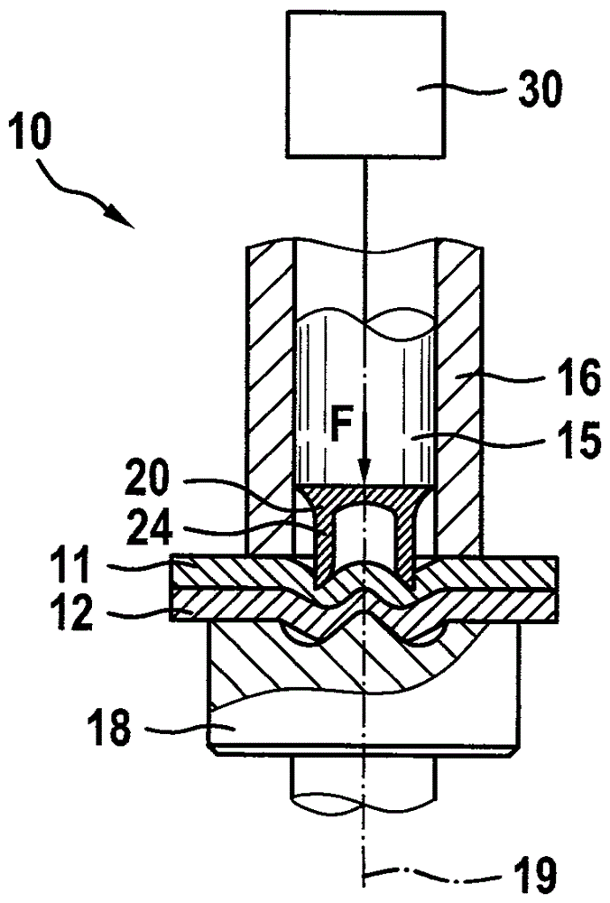
[0022] exist Figure 1a Riveting device 10 is shown in various stages of execution of the riveting method in to 1d. The riveting device 10 has an embossment 15 which, for example, has a circular cross section.

[0023] The embossing 15 is surrounded radially by a sleeve-shaped hold-down device 16 and is arranged displaceably in the longitudinal direction relative to this hold-down device. In particular, the embossing 15 is coupled to a drive (not shown here), for example a hydraulic or pneumatic drive, which is used to apply the force F required for pressing the rivet 20 into the two components 11 , 12 . .

[0024] Likewise, the pressing device 16 is provided for pressing with a pressing force against the surface of the component 11 facing the embossing 15 . For this purpose, for example, a separate drive can be provided. However, the hold-down device can also be coupled to the drive of the emboss 15 , for example by means of a spring.

[0025] On the side of the two compo...


PUM


Abstract

The invention relates to a punch rivet (201) with a rivet head (25) and a rivet shank (24) connected to the rivet head, wherein the rivet shank (24) has at least one projection (241) outwardly protruding from a surface of the rivet shank (24).

Description

technical field [0001] The invention relates to a punch with a rivet head and a shank connected to the head and to the use of such a punch in a vibrated punch riveting method. Background technique [0002] The method for punching riveting is used to connect at least two components (joint pairs) which are in particular planar in the connection region. The punch riveting method is characterized in that no prefabricated holes are required for the components to be connected to each other. In fact, the punch rivet can be pressed into at least two components by means of an embossing or impression, wherein it is ensured by a correspondingly shaped (for example in the form of a negative) counter-holder which cooperates with the impression that The rivet or the component is deformed in a specific manner in order to produce a non-positive and form-fit connection between the components. [0003] Furthermore, ultrasonic riveting methods are known, for example, from EP 2 318 161 B1 or ...

Claims


Application Information

Patent Timeline
Patent Type & Authority Applications(China)
IPC IPC(8): F16B19/08
CPCF16B19/08B21J15/025B21J15/12F16B19/086
Inventor F.韦尔克P.卢茨
Owner ROBERT BOSCH GMBH
Why Eureka
Try Eureka