Clamping arm lead screw tension grip

A tension test and lead screw technology, applied in the field of electric power, can solve the problem that the lead screw of the clamping arm cannot be connected to the force, and achieve good benefits.

Pending Publication Date: 2017-02-22
JINHUA POWER TRANSMISSION & DISTRIBUTION ENG +2
View PDF8 Cites 0 Cited by
  • Summary
  • Abstract
  • Description
  • Claims
  • Application Information

AI Technical Summary

Problems solved by technology

[0006] In order to solve the foregoing problems, the present invention provides a new clamp arm screw tension test fixture, which effectively solves the problem that the clamp arm screw cannot be connected to the force on the static load testing machine.

Method used


Image

  • Clamping arm lead screw tension grip

Examples


Embodiment 1

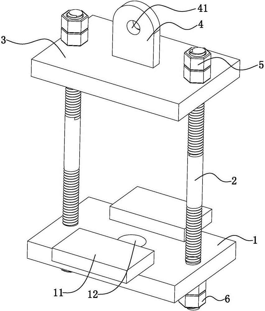
[0022] The invention provides a jig for tensile test of a locking arm lead screw.

[0023] In this embodiment, the jig for pulling force test of the arm screw is installed on the static load testing machine, and includes a traction plate 1 for pulling the arm screw to be tested, a pull bar 2 for pulling the traction plate 1, and a pull bar 2 for pulling the pull plate 1. The pulling plate 3 of the pulling rod 2 and the connecting piece 4 used to connect the arm screw tensile test fixture to the static load testing machine; the connecting piece 4 is welded to the pulling plate 3, and the pulling plate 3 is a rectangular plate with two first connections The two first connecting holes are respectively located near the midpoint of the short side of the rectangular plate. The traction plate 1 adopts a rectangular plate and is provided with two second connecting holes, and the two second connecting holes are respectively located near the short sides of the rectangular plate. Point p...


PUM


Abstract

The invention discloses a novel clamping arm lead screw tension grip which is characterized by comprising a draw plate, a draw rod for drawing the draw plate, a pull plate for pulling the draw rod, and a connecting piece, wherein the connecting piece is connected to the pull plate; and the draw plate is provided with a through hole. The clamping arm lead screw tension grip effectively solves the problem that the clamping groove lead screw is incapable of connection and acting on a dead load tester.

Description

[0001] 【Technical field】 [0002] The invention relates to the field of electric power, in particular to a jig for clamping arm screw tension test. [0003] 【Background technique】 [0004] The clamp arm screw is mainly used in the disassembly and replacement of the insulator string on the line iron tower. The clamp arm of the clamp arm screw is clamped on the cross arm of the iron tower, and the other end is connected to the wire of the insulator string through a pull plate or a pull rod. At the end, the gravity of the wire is applied to the lead screw by the rocker arm to control the tension to replace the insulator string. Therefore, the safety performance of the clamp arm lead screw must be reliable. According to regulations, the arm screw should be subjected to a static load test, but due to the particularity of the shape of the arm, the use of angle steel connection will cause the non-linear stress angle steel to break, so that the arm screw cannot be directly installed on...

Claims


Application Information

Patent Timeline
Patent Type & Authority Applications(China)
IPC IPC(8): G01N3/04
CPCG01N3/04G01N2203/0017G01N2203/0423
Inventor 吴尊东温家铭汤春俊吕大青席思庆方雁叶卫忠邵建标吴锦丰
Owner JINHUA POWER TRANSMISSION & DISTRIBUTION ENG
Why Eureka
Try Eureka