Clamping slot lead screw tension test fixture

A technology of tension test and lead screw, which is applied in the field of electric power, can solve the problem that the lead screw of the slot cannot be connected and exert force, and achieve good benefits

Pending Publication Date: 2017-03-15
JINHUA POWER TRANSMISSION & DISTRIBUTION ENG +2
View PDF10 Cites 0 Cited by
  • Summary
  • Abstract
  • Description
  • Claims
  • Application Information

AI Technical Summary

Problems solved by technology

[0006] In order to solve the aforementioned problems, the present invention provides a new type of tension test fixture for the slotted screw, which effectively solves the problem that the slotted screw cannot be connected to the static load testing machine.

Method used


Image

  • Clamping slot lead screw tension test fixture

Examples


Embodiment 1

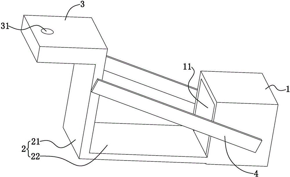
[0022] The invention provides a tension test fixture for a slotted lead screw.

[0023] In this embodiment, the slotted lead screw tensile test fixture, the slotted screw tensile test fixture is installed on the static load testing machine, including: a clamp body 1 provided with an accommodation chamber 11; used to connect the slotted screw tensile test fixture to the static load tester The first connector 3 of the load testing machine; and the second connector 2 connecting the clamp body 1 and the first connector 3; the accommodation chamber 11 is provided with an opening, the clamp body 1 is a hexahedron, the accommodation chamber 11 is a hexahedron, and the accommodation chamber 11 Put the side wall of the slot into the slot of the screw to be tested, and at the same time, the opening is facing the static load testing machine, which determines the direction in which the static load testing machine applies force to the screw to be tested through the slot screw tension test f...


PUM


Abstract

The invention discloses a novel clamping slot lead screw tension test fixture, and is characterized in that the clamping slot lead screw tension test fixture comprises a fixture body, a first connection piece for connecting the clamping slot lead screw tension test fixture to a static load test machine, and a second connection piece for connecting the fixture body with the first connection piece. The problem that a clamping slot lead screw cannot be connected and put forth force on the static load test machine is effectively solved.

Description

[0001] 【Technical field】 [0002] The invention relates to the field of electric power, in particular to a tension test fixture for a slotted lead screw. [0003] 【Background technique】 [0004] The slotted screw is mainly used in the disassembly and replacement of the insulator string on the line iron tower. The slotted screw is stuck on the cross arm on the tower, and the other end is connected to the wire of the insulator string through a pull plate or a pull rod. At the end, the gravity of the wire is applied to the lead screw through the rocker arm to control the tension to replace the insulator string. Therefore, the safety performance of the slot lead screw must be reliable. According to regulations, the slotted screw should be subjected to a static load test, but due to the particularity of the slot shape, the use of angle steel connection will cause the non-linear stress angle steel to break, so that the slotted screw cannot be directly installed on the static load tes...

Claims


Application Information

Patent Timeline
Patent Type & Authority Applications(China)
IPC IPC(8): G01N3/04
CPCG01N3/04G01N2203/04G01N2203/0017
Inventor 吴尊东温家铭汤春俊吕大青席思庆方雁叶卫忠邵建标吴锦丰
Owner JINHUA POWER TRANSMISSION & DISTRIBUTION ENG
Why Eureka
Try Eureka