Design method for centrifugal ventilator adopting honeycomb structure

A technology of honeycomb structure and design method, applied in the direction of design optimization/simulation, instrumentation, calculation, etc., can solve the problems of how to design centrifugal ventilator and low performance of oil and gas separation without data, and achieve the effect of saving design cost

Active Publication Date: 2017-02-22
AECC SHENYANG ENGINE RES INST
View PDF2 Cites 15 Cited by
  • Summary
  • Abstract
  • Description
  • Claims
  • Application Information

AI Technical Summary

Problems solved by technology

At present, the design structure of domestic centrifugal ventilator is generally radial plate type. This kind of centrifugal ventilator has simple structure and high reliability, but the efficiency of oil and gas separation is generally not high, which cannot meet the needs of long-endurance engines.
[0004] Foreign data show that the centrifugal ventilator with honeycomb structure has high separation efficiency and has been applied to the lubricating oil system of engines with low lubricating oil consumption. However, due to some reasons, there is no data showing how to design the centrifugal ventilator with honeycomb structure.

Method used


Image

  • Design method for centrifugal ventilator adopting honeycomb structure
  • Design method for centrifugal ventilator adopting honeycomb structure
  • Design method for centrifugal ventilator adopting honeycomb structure

Examples


Embodiment Construction

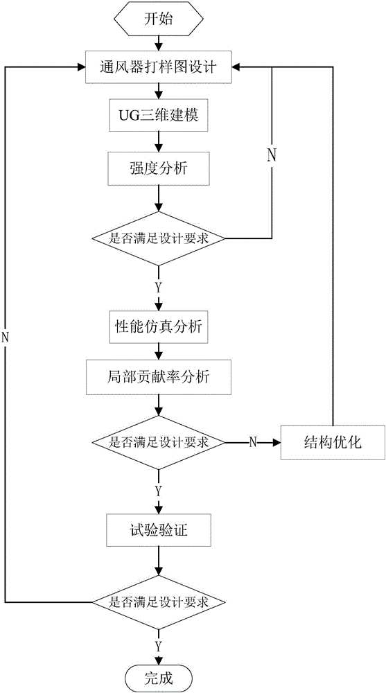
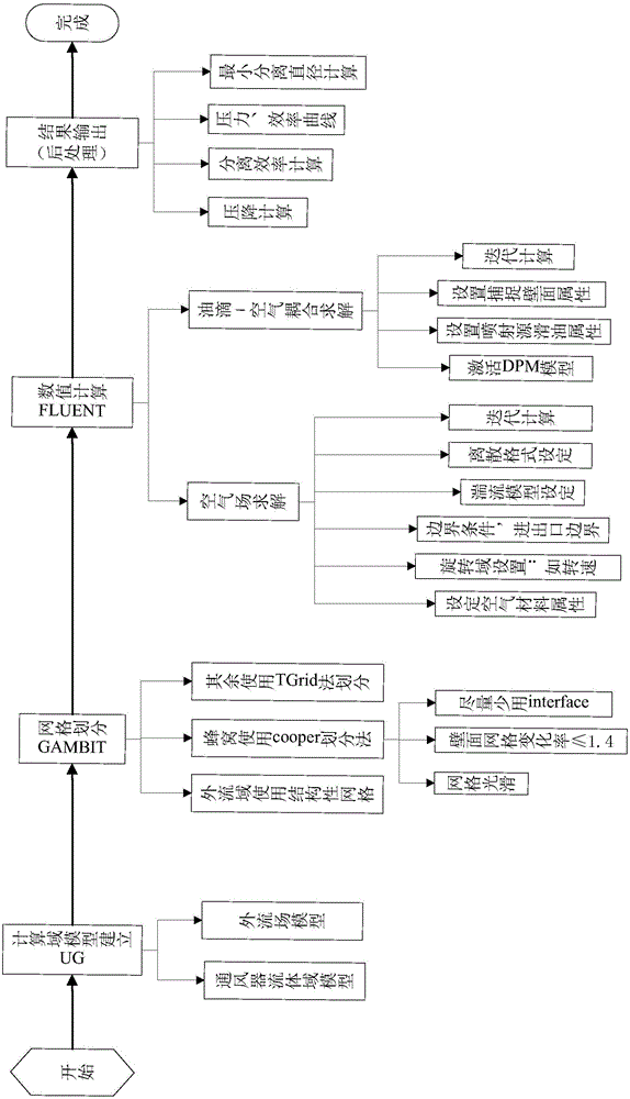
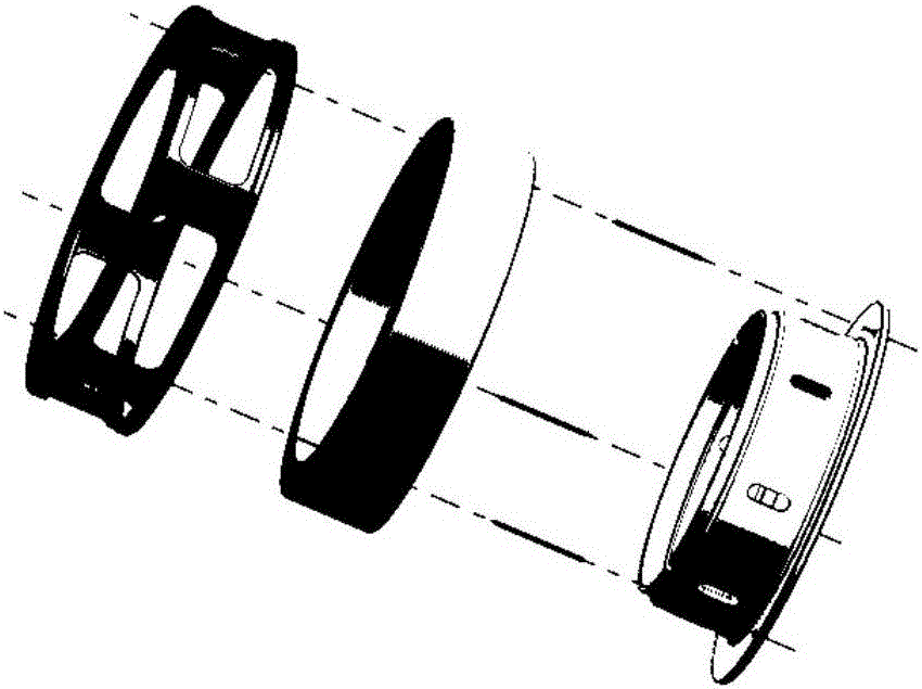
[0042] In order to make the objectives, technical solutions and advantages of the present invention clearer, the technical solutions in the embodiments of the present invention will be described in more detail below in conjunction with the drawings in the embodiments of the present invention. In the drawings, the same or similar reference numerals represent the same or similar elements or elements having the same or similar functions throughout. The described embodiments are some, but not all, embodiments of the invention. The embodiments described below by referring to the figures are exemplary and are intended to explain the present invention and should not be construed as limiting the present invention. Based on the embodiments of the present invention, all other embodiments obtained by persons of ordinary skill in the art without making creative efforts belong to the protection scope of the present invention. Embodiments of the present invention will be described in detai...


PUM


Abstract

The invention relates to a design method for a centrifugal ventilator adopting a honeycomb structure. The method comprises the steps of S1: performing preliminary design of a ventilator structure according to design input requirements; S2: performing three-dimensional modeling; S3: performing strength analysis whether the ventilator meets a strength requirement or not by utilizing a finite element method, and if yes, continuing to perform the step S4, otherwise, returning to the step S1; S4: performing performance simulation analysis of the ventilator by utilizing computational fluid mechanics software; S5: performing local contribution rate analysis by integrating simulation analysis results of state points; S6: repeating the steps S2-S5, adjusting the ventilator structure, and performing structure optimization on the ventilator; S7: performing experimental verification; and S8: repeating the steps S2-S7 to obtain the ventilator meeting the need, thereby finishing the design. According to the design method for the centrifugal ventilator adopting the honeycomb structure, the performance of the novel honeycomb centrifugal ventilator adopting the porous structure is subjected to simulation analysis through the finite element simulation analysis method to pre-estimate the design effect, thereby reducing the design cost.

Description

technical field [0001] The invention belongs to the field of aviation gas turbine structure design, and in particular relates to a design method of a honeycomb structure centrifugal ventilator. Background technique [0002] The aviation gas turbine engine lubricating oil system is an important part of the aviation gas turbine engine. It is mainly responsible for the lubrication of the engine's high and low pressure rotor fulcrum bearings, transmission gears and other components. Drain out of the engine, and at the same time separate the oil and gas, keep the lubricating oil in the bearing cavity to continue to participate in the circulation, and discharge the air out of the engine. Therefore, the ventilator is an indispensable key component of the lubricating oil system. The performance of the separator determines the amount of lubricating oil discharged from the engine per unit time, and the amount of lubricating oil on the engine is limited. A large amount of consumption ...

Claims


Application Information

Patent Timeline
Patent Type & Authority Applications(China)
IPC IPC(8): G06F17/50
CPCG06F30/23
Inventor 刘晨昊谷俊周志宏毛福荣焦自涛
Owner AECC SHENYANG ENGINE RES INST
Why Eureka
Try Eureka