Multi-frequency navigation terminal antenna

A navigation terminal and antenna technology, which is applied in the field of communication and navigation, can solve the problems of increasing and unfavorable miniaturization of antenna volume, and achieve the effects of reducing structural volume, low dielectric loss, and high dielectric constant

Inactive Publication Date: 2017-02-22
ANHUI SUN CREATE ELECTRONICS
View PDF0 Cites 11 Cited by
  • Summary
  • Abstract
  • Description
  • Claims
  • Application Information

AI Technical Summary

Problems solved by technology

However, in actual production, it was found that since each layer of the patch with the feed probe needs to arrange a circle of metallized vias outside the feed hole, this makes it necessary not only for the feed hole at the current layer patch An area is reserved on the periphery for metallized vias to penetrate, and at the same time, the bottom patch must also have enough area to accommodate the densely packed metallized vias that are stacked and penetrated from the upper layer and even the upper layer. It can only be guaranteed by increasing the patch area of ​​the bottom layer, which is obviously extremely unfavorable to the current miniaturization requirements of the antenna volume

Method used


Image

  • Multi-frequency navigation terminal antenna
  • Multi-frequency navigation terminal antenna
  • Multi-frequency navigation terminal antenna

Examples


Embodiment Construction

[0039] For ease of understanding, the specific implementation structure and workflow of the present invention are described below in conjunction with the accompanying drawings:

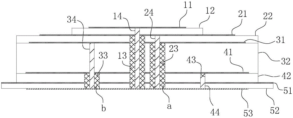
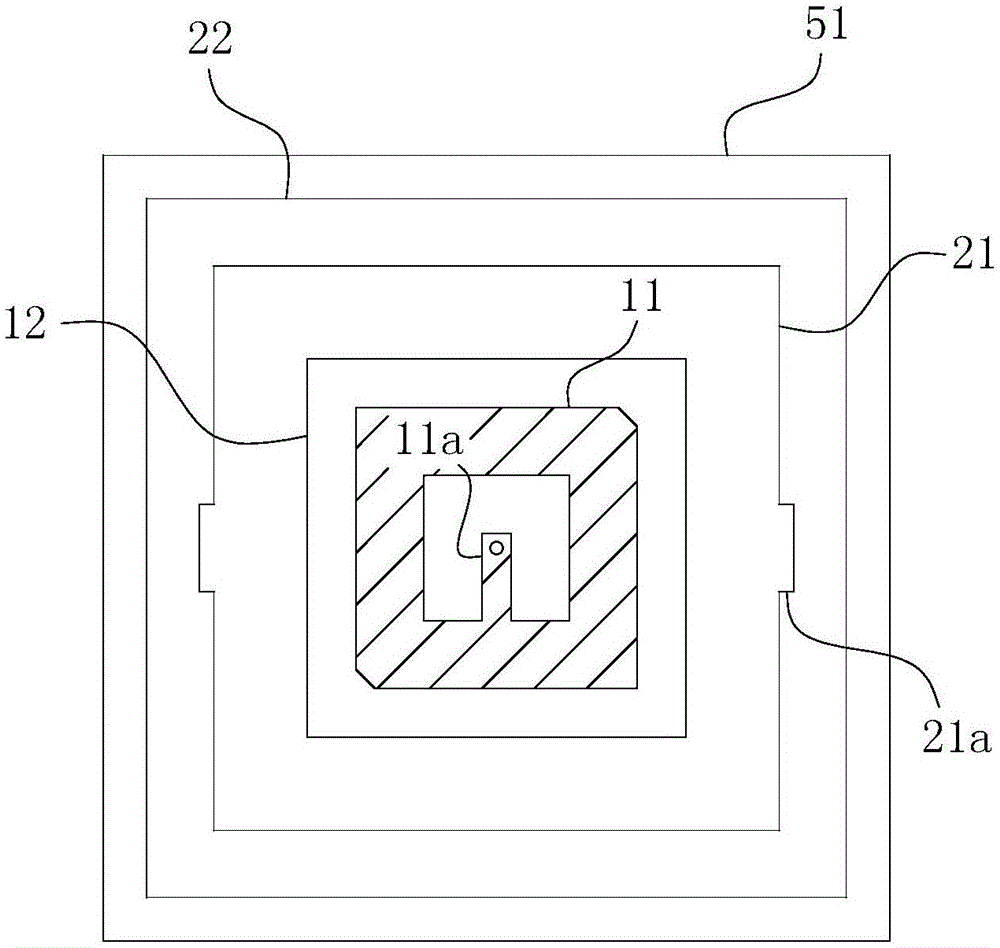
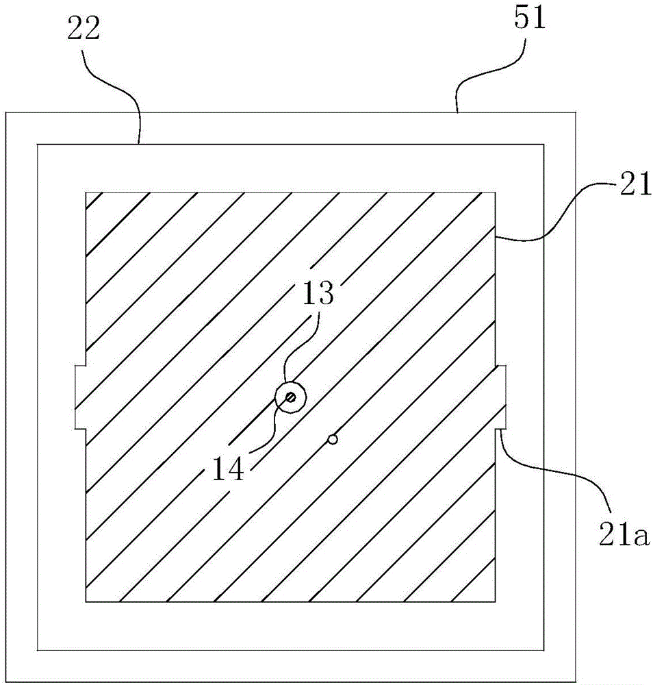
[0040] Concrete structure of the present invention, as Figure 1-5 As shown, it includes the first layer of microstrip antenna, the second layer of microstrip antenna, the third layer of microstrip antenna, the fourth layer of microstrip antenna, the bottom feeding network, feeding probes, metallized vias, etc. The first-layer microstrip antenna includes a first-layer microstrip patch 11 and a first-layer dielectric substrate 12 . The first layer of microstrip patch 11 is a square thin plate structure, and cut diagonally along the diagonal; the first layer of microstrip patch 11 has a "U" formed by protruding rectangular branches 11a at the central square hole position letter gap. The second layer of microstrip antenna includes a second layer of micro-dot patch 21 and a second layer of dielectric su...


PUM


Abstract

The invention belongs to the technical field of communication and navigation and in particular relates to a multi-frequency navigation terminal antenna. A top-layer feeding point is arranged at the center of a first-layer micro-strip patch; a central feeding hole is vertically formed in the top-layer feeding point; a first feeding point is arranged at a second-layer micro-strip patch; a first feeding hole is vertically formed in the first feeding point; a second feeding point is arranged at a third-layer micro-strip patch; a second feeding hole is vertically formed in the second feeding point; a third feeding point is arranged at a fourth-layer micro-strip patch. The antenna also comprises first short circuit metallized via holes and second short circuit metallized via holes which are used for eliminating coupling influence of feeding probes in all the feeding holes. The multi-frequency navigation terminal antenna disclosed by the invention can cover L band and S band of first-generation Beidou, B1 band and B3 band of second-generation Beidou and L1 band of a GPS (Global Positioning System); the demands on minimization and lightness of antenna size are met while good impedance bandwidth, axial ratio bandwidth and high-gain performance can be guaranteed.

Description

technical field [0001] The invention belongs to the technical field of communication and navigation, and in particular relates to a multi-frequency navigation terminal antenna. Background technique [0002] The Beidou satellite navigation system is a global satellite navigation and communication system independently developed by my country. It is also known as the world's four major satellite navigation systems together with GPS in the United States, GLONASS in Russia, and Galileo in Europe. With the gradual improvement and wide application of the Beidou navigation system, the research on its terminal antenna is becoming more and more extensive and in-depth. The current navigation terminal antenna mainly has technical problems such as difficulty in terminal equipment integration, narrow frequency band, inability to accommodate multiple operating frequency points, and even poor isolation of multi-band ports. In view of this, the current multi-frequency circularly polarized a...

Claims


Application Information

Patent Timeline
Patent Type & Authority Applications(China)
IPC IPC(8): H01Q1/38H01Q1/50H01Q1/52H01Q15/24H01Q5/28
CPCH01Q1/38H01Q1/50H01Q1/521H01Q5/28H01Q15/24
Inventor 李运志贾蕾
Owner ANHUI SUN CREATE ELECTRONICS
Why Eureka
Try Eureka