Spiral drilling grouting structure and grouting control system thereof

A technology of control system and helical drill rod, which is applied in the direction of rotary drilling, percussion drilling, rotary drilling rigs, etc., can solve the problems of heavy weight, high torque requirements of drilling rigs, and different raw material particles, so as to improve efficiency, The effect of reducing manufacturing cost and improving strength

Pending Publication Date: 2021-09-07
江西东锐机械有限公司 +1
View PDF0 Cites 0 Cited by
  • Summary
  • Abstract
  • Description
  • Claims
  • Application Information

AI Technical Summary

Problems solved by technology

Traditional undisturbed soil excavation foundations (excavation piles), rock embedded foundations and other types, the pile diameter is relatively large, generally more than 1m, and the buried depth is relatively deep (6m-30m), which requires a large torsion force of the drilling rig. Excavation machinery requires high-torque equipment to form holes. High-torque equipment is bulky and heavy, and it is difficult to go up the mountain. Mechanized construction cannot be realized.
[0003] Because the existing drill rods are mainly drilled through the auger drill rods during the drilling process, and when the drilling depth reaches a relatively deep level, the existing drill rods cannot meet the requirements of the drilling depth. When the auger drill rods When the height of the grouting system is high, the grouting system is not convenient for grouting at this time, and the raw materials purchased by the existing grouting control system have different particles, which seriously affects the effect of stirring and mixing, making the grouting The effect of the grouting is not good, and the grouting strength cannot meet the requirements. Therefore, the auger drilling grouting structure and its grouting control system are proposed to solve the above problems

Method used


Image

  • Spiral drilling grouting structure and grouting control system thereof
  • Spiral drilling grouting structure and grouting control system thereof
  • Spiral drilling grouting structure and grouting control system thereof

Examples


Embodiment Construction

[0033] The present invention will be further described below in conjunction with accompanying drawing, protection scope of the present invention is not limited to the following:

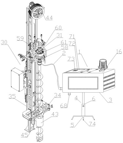
[0034] Such as Figure 1~10 As shown, the auger drills into the grouting structure and its grouting control system, which includes a grouting control system 1, and the grouting control system 1 includes a grouting hose 2 and a grouting device 3, and the grouting device 3 The bottom is provided with a lifting device 4, and the setting of the lifting device 4 enables the grouting control system to adjust its height according to the environment. The lifting device 4 includes three claws 5 and a telescopic rod 6. Connected, the grouting device 3 is a structure with a cavity inside, and the inside of the cavity is provided with a first cavity 7, a second cavity 8 and a third cavity 9;

[0035] The inside of the first cavity 7 is provided with a stirring system and a feeding system cooperating with the st...


PUM


Abstract

The invention discloses a spiral drilling grouting structure and a grouting control system thereof. The grouting control system and the spiral drilling grouting structure are included, the grouting control system comprises a grouting hose and a grouting device, a lifting device is arranged at the bottom of the grouting device and comprises three jaws and a telescopic rod, one end of the telescopic rod is connected with the three jaws, the grouting device is of a structure internally provided with a cavity, and a first cavity, a second cavity and a third cavity are formed in the cavity; and the spiral drilling grouting structure comprises a device body, the device body comprises a propelling beam system, a grouting connector, spiral drilling rods, a rod unloading mechanism and a support, the grouting connector comprises a hollow cylinder, and the hollow cylinder is sleeved with a rotary adjusting cylinder. The spiral drilling grouting structure and the grouting control system have the beneficial effects that crushing and stirring are integrated in the grouting control system, so that input building materials can be crushed while a motor output shaft I rotates, the cost is reduced, and the applicability of a drilling machine is improved through the arrangement of the multiple sections of spiral drill rods in the spiral drilling grouting structure.

Description

technical field [0001] The invention relates to the technical field of auger drilling grouting, in particular to an auger drilling grouting structure and a grouting control system thereof. Background technique [0002] The mountainous foundation of the transmission line project has complex topography, complex geological conditions, and poor traffic conditions (there are no ready-made roads and in many cases there are several-meter-high fault cliffs blocking road construction), and the construction of cableways is also manual digging of foundation pits and pile holes. Traditional undisturbed soil excavation foundations (excavation piles), rock embedded foundations and other types, the pile diameter is relatively large, generally more than 1m, and the buried depth is relatively deep (6m-30m), which requires a large torsion force of the drilling rig. Excavation machinery requires high-torque equipment to form holes. High-torque equipment is bulky and heavy, and it is difficult ...

Claims


Application Information

Patent Timeline
Patent Type & Authority Applications(China)
IPC IPC(8): E21B3/02E21B15/00E21B19/18E02D15/02E02D15/04
CPCE21B3/022E21B15/00E21B19/18E02D15/02E02D15/04
Inventor 刘锐军方晴张江
Owner 江西东锐机械有限公司
Why Eureka
Try Eureka