A multifunctional drill clamp device

A multi-functional, drill-clamp technology, applied in the field of drilling processing machinery, can solve problems such as inconvenient measurement, moving parts position, drilling deviation, etc. Effect

Active Publication Date: 2017-10-10
GUIZHOU AEROSPACE IND SCHOOL
View PDF12 Cites 0 Cited by
  • Summary
  • Abstract
  • Description
  • Claims
  • Application Information

AI Technical Summary

Problems solved by technology

[0003] (1) Since the machine vise is used by manual movement, when machining a hole with an angle requirement, the drilling can only be positioned by scribing, proofing and punching, which cannot guarantee the drilling accuracy and is inconvenient Measurement;
[0004] (2) When punching the positioning hole, because the position of the part cannot be moved accurately, the hole is deviated, and the position cannot be accurately located during the calibration deviation, and the scrap rate of the part is increased due to the deviation of the punching hole;
[0005] (3) When arranging holes, it is impossible to move a certain distance accurately, so that when arranging holes, the hole spacing is too large, which makes it difficult to discharge materials, and the hole spacing is too small, which will cause the drill bit to slip or even break, and even cause parts to be scrapped

Method used


Image

  • A multifunctional drill clamp device
  • A multifunctional drill clamp device
  • A multifunctional drill clamp device

Examples


specific Embodiment approach

[0042] DETAILED DESCRIPTION OF THE PREFERRED EMBODIMENTS: The technical solution of the present invention will be further described below in conjunction with the accompanying drawings, but the scope of protection is not limited to the description.

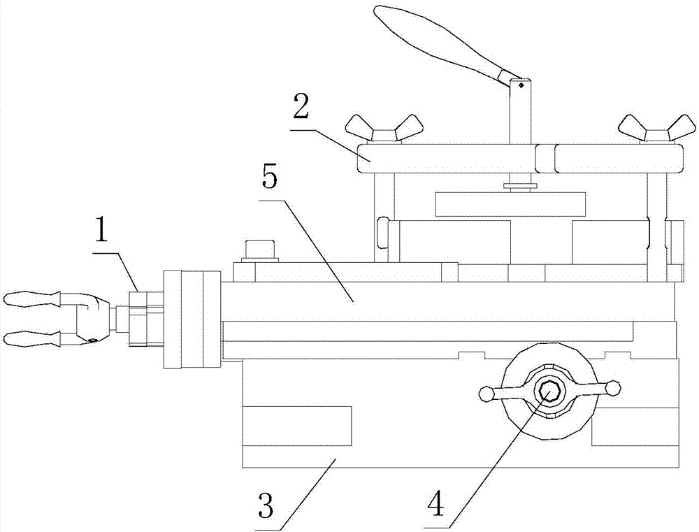
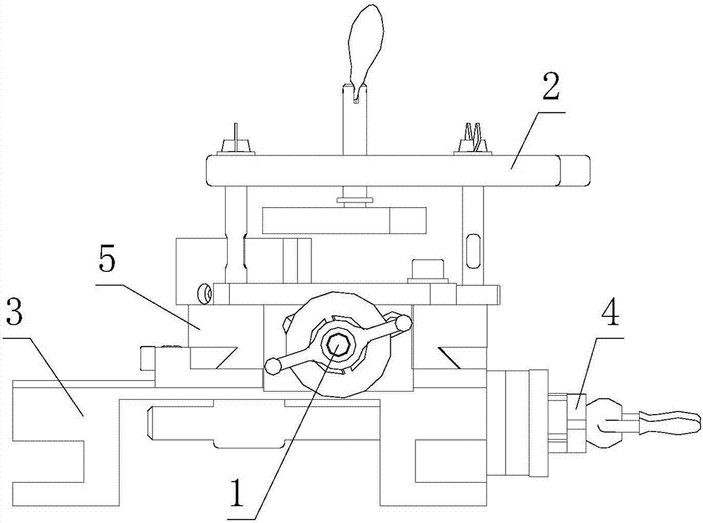
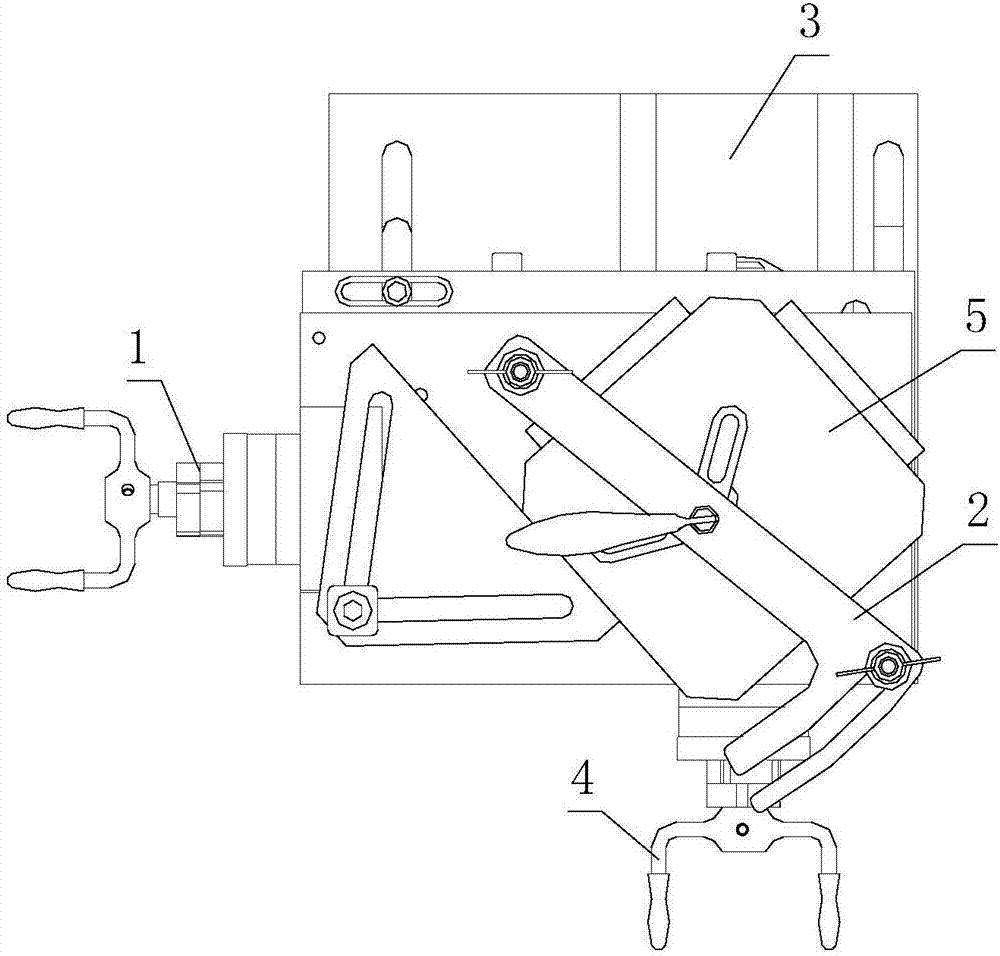
[0043] Such as Figure 1 to Figure 14 As shown, a kind of multifunctional drill chuck device according to the present invention includes a lateral movement operation mechanism 1, a pressing mechanism 2, a base 3, a longitudinal movement operation mechanism 4 and a vertical and horizontal movement mechanism 5, and the vertical and horizontal movement mechanism 5 It is composed of a lower supporting plate 51 and an upper supporting plate 53, wherein the lower supporting plate 51 and the upper supporting plate 53 are connected by a dovetail groove, the base 3 is provided with a slide rail 33, and the base 3 is connected with the set via the slide rail 33 Fitted and connected with the concave groove 511 at the bottom of the lower palle...


PUM


Abstract

The invention discloses a multifunctional drilling and clamping device. The multifunctional drilling and clamping device comprises a transverse moving operation mechanism, a compressing mechanism, a base, a longitudinal moving operation mechanism and a longitudinal and transverse moving mechanism. The longitudinal and transverse moving mechanism is composed of a lower bracket plate and an upper bracket plate which are connected in a matched through a dovetail groove. The base is provided with a sliding rail and connected with a concave groove in the bottom of the lower bracket plate through the sliding rail in a matched mode. The compressing mechanism is installed above the longitudinal and transverse moving mechanism and connected with the upper bracket plate. The transverse moving operation mechanism is installed on the lower bracket plate. The longitudinal moving operation mechanism is installed on the base. The multifunctional drilling and clamping device can move longitudinally and transversely, is convenient to operate, is high in moving accuracy, and realizes machining of longitudinal and transverse holes in different positions. As a rotary disc and the upper bracket plate are matched through a small-interval round shaft, it is guaranteed that the rotary disc and the upper bracket plate can rotate relatively freely, the revolving accuracy is high, and hole drilling at any angle within the range of 360 degrees can be realized.

Description

technical field [0001] The invention belongs to the technical field of drilling machinery, and in particular relates to a multifunctional drill clamp device. Background technique [0002] At present, in the fitter (drilling and milling) processing, the most commonly used drill clamp device is the machine vise, and the use of the machine vise to drill holes mainly has the following shortcomings: [0003] (1) Since the machine vise is used by manual movement, when machining a hole with an angle requirement, the drilling can only be positioned by scribing, proofing and punching, which cannot guarantee the drilling accuracy and is inconvenient Measurement; [0004] (2) When punching the positioning hole, because the position of the part cannot be moved accurately, the hole is deviated, and the position cannot be accurately located during the calibration deviation, and the scrap rate of the part is increased due to the deviation of the punching hole; [0005] (3) When arranging...

Claims


Application Information

Patent Timeline
Patent Type & Authority Patents(China)
IPC IPC(8): B23Q3/06B23Q1/26
CPCB23Q1/4809B23Q3/06
Inventor 叶显金钱卫吴超
Owner GUIZHOU AEROSPACE IND SCHOOL
Why Eureka
Try Eureka