

Antenna switching method and apparatus
An antenna switching and antenna technology, applied in the field of communication, can solve problems such as the influence of the stability of electronic equipment
- Summary
- Abstract
- Description
- Claims
- Application Information
AI Technical Summary
Problems solved by technology
Method used
Image

Examples
Embodiment 1
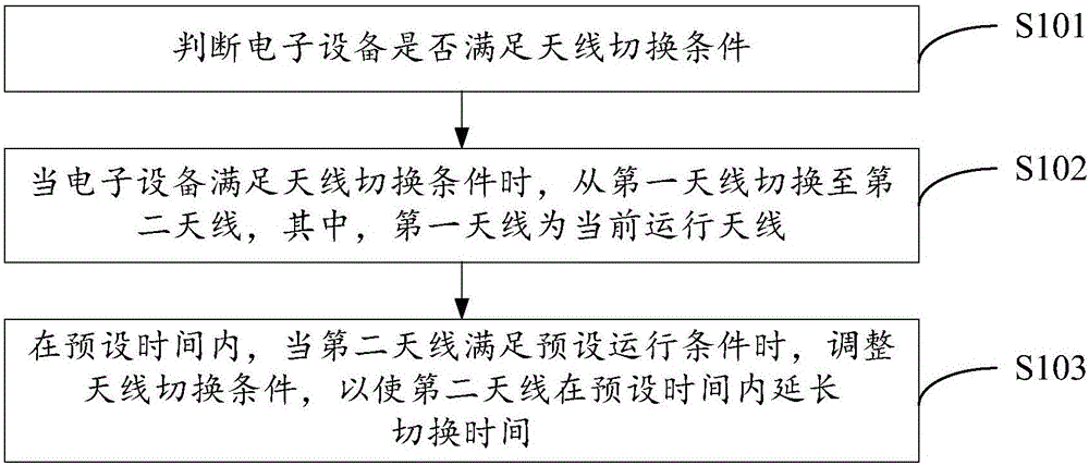
[0042] figure 1 It is a schematic flowchart of the antenna switching method provided in Embodiment 1 of the present invention. The antenna switching method is applied to electronic equipment, and the electronic equipment includes two antennas, such as mobile phones and routers. Such as figure 1 As shown, the antenna switching method may include the following steps:
[0043] S101: Determine whether the electronic device meets an antenna switching condition.
[0044] In this embodiment, the electronic device includes two antennas, and the antennas can be switched when the electronic device is running. The foregoing antenna switching condition is a preset switching condition, and the foregoing antenna switching condition is used to perform antenna switching when the electronic device meets the antenna switching condition. The antenna switching conditions of each antenna are the same. The specific antenna switching condition may be set as required, for example, switching may ...
Embodiment 2
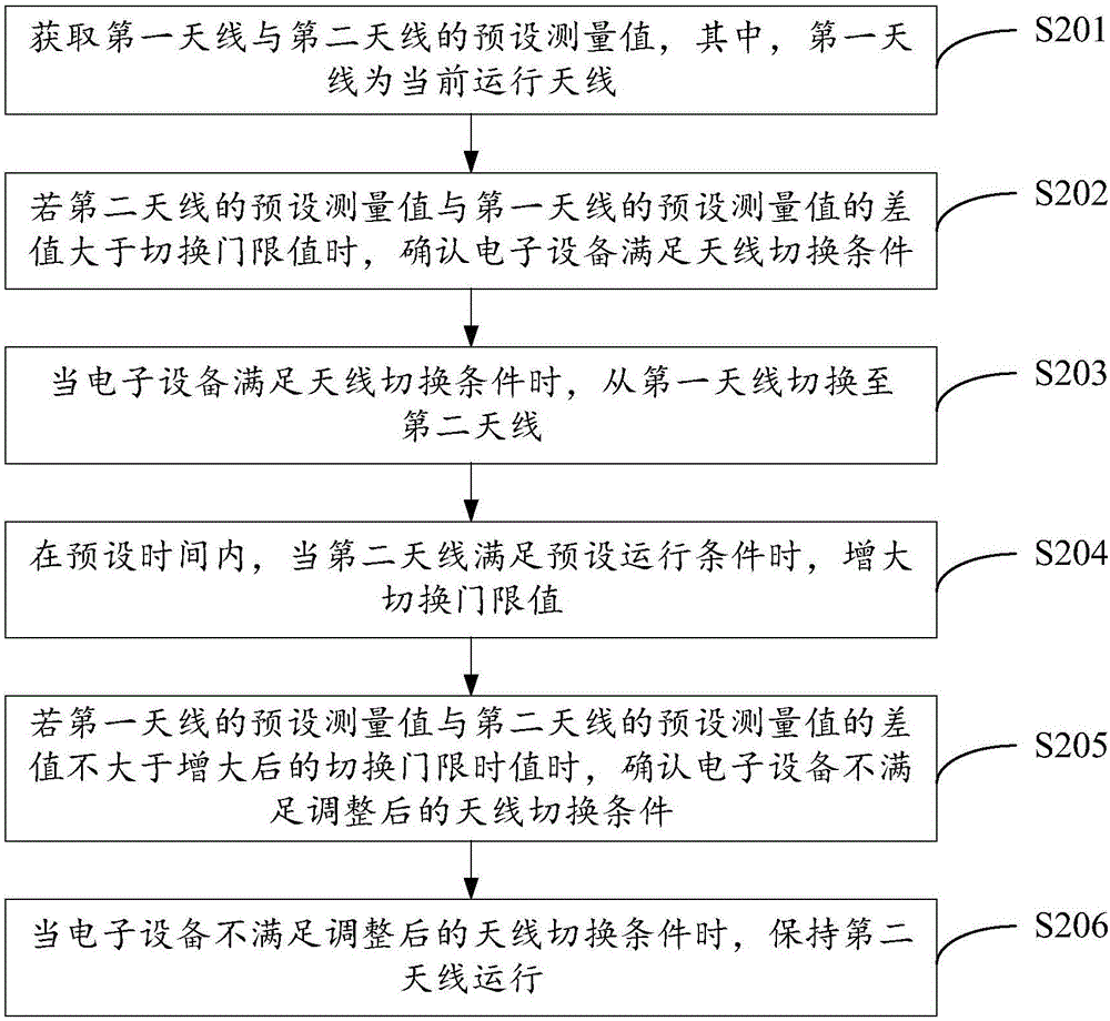
[0054] figure 2 It is a schematic flowchart of the antenna switching method provided in Embodiment 2 of the present invention. The antenna switching method is applied to electronic equipment, and the electronic equipment includes two antennas, such as mobile phones and routers. Such as figure 2 As shown, the antenna switching method may include the following steps:
[0055] S201: Acquire preset measurement values of the first antenna and the second antenna, where the first antenna is a currently operating antenna.
[0056] In this embodiment, the electronic device includes two antennas, and the antennas can be switched when the electronic device is running. The above-mentioned first antenna is a currently operating antenna, that is, the current electronic device uses the first antenna to operate. The above-mentioned second antenna may be any other antenna in the electronic device except the first antenna.
[0057] The above-mentioned preset measurement values are me...
Embodiment 3
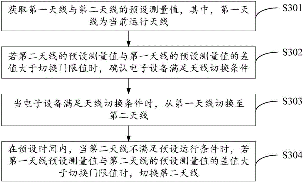
[0084] image 3 It is a schematic flowchart of the antenna switching method provided by Embodiment 3 of the present invention. The antenna switching method is applied to electronic equipment, and the electronic equipment includes two antennas, such as mobile phones and routers. Such as image 3 As shown, the antenna switching method may include the following steps:
[0085] S301: Acquire preset measurement values of the first antenna and the second antenna, where the first antenna is a currently operating antenna.
[0086] Step S301 in this embodiment is consistent with step S201 in Embodiment 2. For details, please refer to the relevant description of Step S201 in Embodiment 2, which will not be repeated here.
[0087] S302: If the difference between the preset measurement value of the second antenna and the preset measurement value of the first antenna is greater than a switching threshold, confirm that the electronic device satisfies the antenna switching condition.
...
PUM
 Abstract
Description
Claims
Application Information