Power factor correction converter

a converter and power factor technology, applied in the field of alternating current to direct current, can solve the problems of large switching loss, increase in the size of the inductor, and high peak value of electromagnetic interference noise, so as to reduce the size and weight, reduce the switching loss, and reduce the effect of switching loss

Active Publication Date: 2010-04-22
MURATA MFG CO LTD
View PDF3 Cites 34 Cited by
  • Summary
  • Abstract
  • Description
  • Claims
  • Application Information

AI Technical Summary

Benefits of technology

[0019]To overcome the problems described above, preferred embodiments of the present invention enable appropriate modulation of a switching frequency without depending on an input voltage and provide a PFC converter that is adaptable to a wide range of input voltages while suppressing a peak of EMI noise in the switching frequency and higher-order frequencies thereof.
[0026]According to various preferred embodiments of the present invention, the following advantages are obtained.
[0028]The switching frequency of the switching circuit is decreased when an instantaneous value of the AC input power supply voltage is at a lower limit or in the vicinity of the lower limit, whereas the switching frequency of the switching circuit is increased when the instantaneous value of the AC input power supply voltage is at an upper limit or in the vicinity of the upper limit. This enables use within a range in which an inductor is not saturated at a time when an input current becomes large without causing an increase in the inductance of the inductor, and the size and weight can be reduced. Also, since the switching frequency of the switching circuit is decreased when an instantaneous value of the voltage of the AC input power supply is at a lower limit or in the vicinity of the lower limit, a switching loss can be reduced.
[0029]A modulation range of the switching frequency of the switching circuit shifts to a low frequency side as a peak value or an effective value of the AC input power supply voltage is higher. Thus, a switching loss can be reduced by decreasing the switching frequency in a range where the inductor is not saturated, and the efficiency can be improved.
[0030]A substantially-rectangular-wave signal generated through waveform shaping of a voltage signal of the AC input power supply is sampled, and the phase of the AC input power supply voltage is detected based on a rise or fall time of the signal. Accordingly, only input information of binary signals is necessary to be handled. This reduces an operation process load, whereby the number of bits of an A / D converter can be advantageously reduced, and the cost and power consumption can be reduced.
[0031]A voltage signal of the AC input power supply is sampled, and the phase of the AC input power supply voltage is detected from at least one of a time when an instantaneous value of the voltage signal reaches a peak, a time when the instantaneous value is a minimum, and a time when the instantaneous value is a predetermined value. Accordingly, a simple voltage dividing resistor circuit may preferably be used as a circuit provided outside a DSP, for example. As a result, the circuit configuration can be simplified, the size can be reduced, and the reliability can be improved.

Problems solved by technology

However, in a typical PFC converter that performs a chopper operation at a given switching frequency, electromagnetic interference (EMI) noise with a high peak value occurs in the switching frequency and higher-order frequencies thereof.
This causes an increase in the size of the inductor.
On the other hand, when the switching frequency is high, a large switching loss occurs.
However, in this case, the following problem arises.

Method used


Image

  • Power factor correction converter
  • Power factor correction converter
  • Power factor correction converter

Examples


first preferred embodiment

[0046]A PFC converter according to a first preferred embodiment of the present invention will be described with reference to FIGS. 3 to 8B.

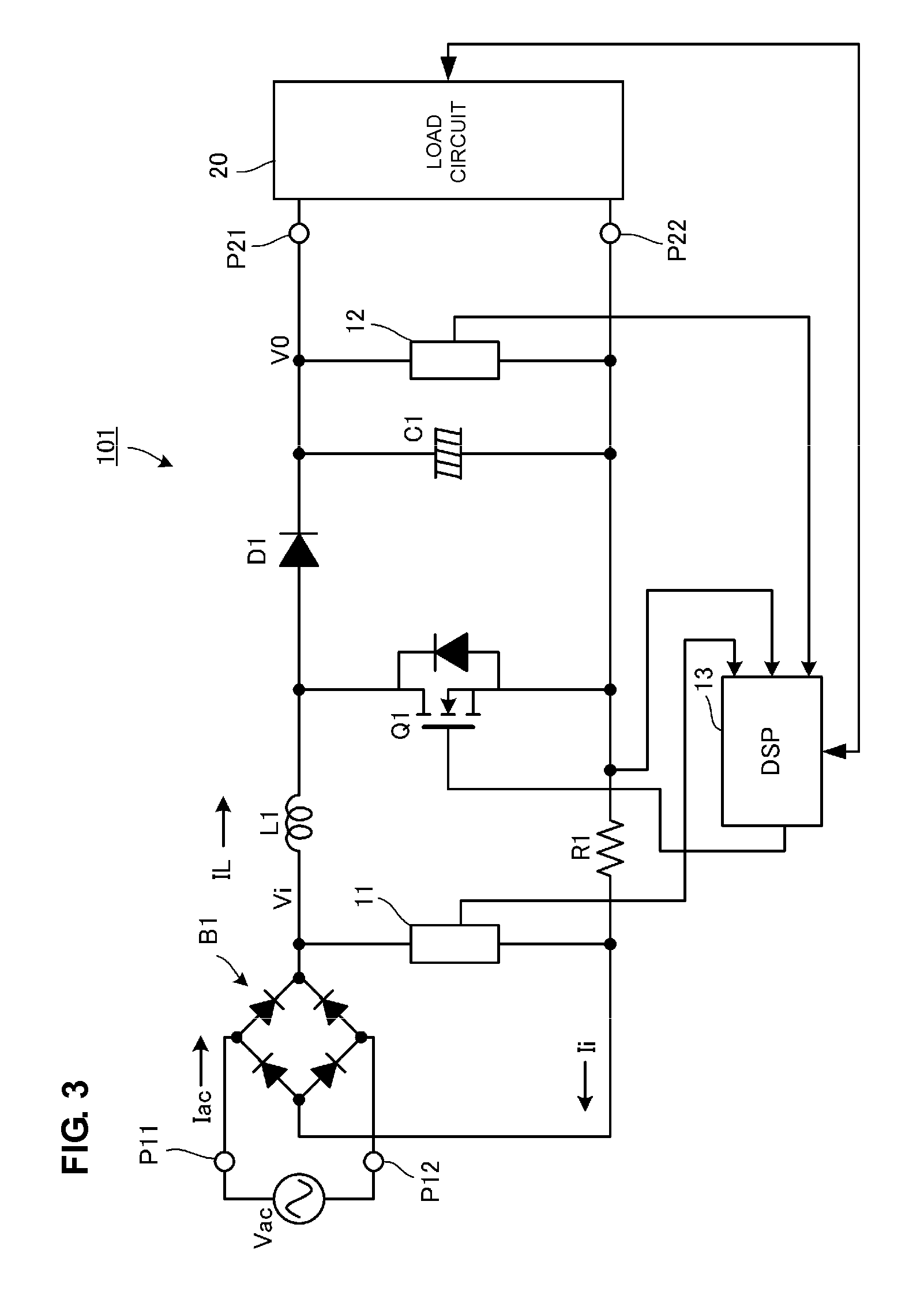
[0047]FIG. 3 is a circuit diagram of the PFC converter according to the first preferred embodiment of the present invention. In FIG. 3, reference numerals P11 and P12 denote input ports of the PFC converter 101, and reference numerals P21 and P22 denote output ports of the PFC converter 101. An AC input power supply Vac, which is a commercial AC power supply, is input to the input ports P11 and P12, and a load circuit 20 is connected to the output ports P21 and P22.

[0048]The load circuit 20 is, for example, a circuit of a DC-DC converter and an electronic apparatus that is supplied with power by the DC-DC converter.

[0049]In an input stage of the PFC converter 101, a diode bridge B1 that performs full-wave rectification on the AC input power supply Vac is provided. On the output side of the diode bridge B1, a series circuit including an inductor L...

second preferred embodiment

[0069]In the first preferred embodiment, a sinusoidal wave that is synchronized with an input voltage is preferably generated in the digital signal processing circuit 13. In the second preferred embodiment of the present invention, an input voltage signal preferably is detected and is normalized, and the normalized signal is used as a signal for frequency modulation. The circuit configuration of a PFC converter is substantially the same as that illustrated in FIG. 3.

[0070]FIG. 9 is a diagram illustrating a process of a digital signal control circuit of the PFC converter according to the second preferred embodiment. In FIG. 9, an input voltage V1 is expressed by the following equation.

Vi(t)=|Vrms sin(ωact)|

[0071]Here, Vrms represents an effective value of the input voltage V1, and ωac represents an angular frequency of Vi(t).

[0072]This voltage signal is normalized using the effective value thereof, and the normalized signal is expressed by Va(t) in the following equation.

Va(t)=Vi(t) / ...

third preferred embodiment

[0076]In the first and second preferred embodiments, a voltage signal of a full-wave rectification input voltage preferably is directly input to the digital signal processing circuit in order to detect a voltage waveform of the AC input power supply. In the third preferred embodiment of the present invention, an input voltage is detected based on a current flowing through the inductor L1. The circuit configuration of a PFC converter preferably is substantially the same as that illustrated in FIG. 3.

[0077]FIG. 10 is a diagram illustrating an on time Ton and an off time Toff of the switching element Q1 and a waveform of a current flowing through the inductor L1.

[0078]The current IL flowing through the inductor L1 is detected by the digital signal processing circuit 13 based on a voltage drop of the current detecting resistor R1. The digital signal processing circuit 13 then calculates an instantaneous value of the full-wave rectification input voltage V1 in accordance with the followi...


PUM


Abstract

A power factor correction converter includes a diode bridge arranged to perform full-wave rectification on an AC input power supply, a switching element arranged to perform switching on an output voltage thereof, an inductor arranged to pass a current interrupted by the switching element and to accumulate and emit excitation energy, a diode, and a smoothing capacitor defining a step-up chopper circuit. A digital signal processing circuit detects a phase of an input voltage, and a switching frequency of the switching element is modulated in accordance with the phase. Accordingly, the switching frequency can be appropriately modulated without depending on an input voltage, so that a wide range of input voltages can be accepted while suppressing EMI noise with a peak generated in the switching frequency and higher-order frequency components thereof.

Description

BACKGROUND OF THE INVENTION[0001]1. Field of the Invention[0002]The present invention relates to an alternating current to direct current (AC-DC) converter that receives an AC power supply and that outputs a DC voltage, and particularly to a power factor correction (PFC) converter provided to improve a power factor.[0003]2. Description of the Related Art[0004]In Japan, Europe, and other countries, harmonic current control that is classified in accordance with an application or an input power is performed. In order to respond to such control, a circuit called a PFC converter is added to a power supply of home appliances that are subjected to harmonic current control, whereby measures have been taken to suppress harmonic currents.[0005]In a typical switching power supply device using a commercial AC power supply as an input power supply, the commercial AC power supply is rectified and smoothed so as to be converted to a DC voltage, and switching by a DC-DC converter is performed on th...

Claims


Application Information

Patent Timeline
Patent Type & Authority Applications(United States)
IPC IPC(8): H02M7/217
CPCH02M1/4225Y02B70/126H02M3/157H02M1/44Y02B70/10H02M1/0085
Inventor UNO, YOSHIYUKITOKUGAWA, TOMOKUNIHOSOTANI, TATSUYA
Owner MURATA MFG CO LTD
Why Eureka
Try Eureka