Image processing apparatus and image processing method for transferring image data

a technology of image data and image processing apparatus, which is applied in the field of image processing apparatus and image processing method for transferring image data, can solve the problems of hindering the operation of other devices, affecting the human body, and difficult to take countermeasures against emi (electro magnetic interference), so as to suppress the noise of emi and suppress the transition of data lines.

Active Publication Date: 2017-06-20
CANON KK
View PDF3 Cites 0 Cited by
  • Summary
  • Abstract
  • Description
  • Claims
  • Application Information

AI Technical Summary

Benefits of technology

[0008]The present invention has been made in consideration of such a problem, and provides a technique for effectively suppressing EMI noise by suppressing the transition of data lines of a memory without requiring any redundant memory area.

Problems solved by technology

However, an increase in the electromagnetic radiation of an LSI along with an increase in operating frequency makes it difficult to take countermeasures against EMI (Electro Magnetic Interference).
EMI hinders the operations of other devices and affects the human body.
The technique disclosed in Japanese Patent Laid-Open No. 2008-59449, however, has a problem that it needs a memory area for storing redundancy bits representing the order of bursts.

Method used


Image

  • Image processing apparatus and image processing method for transferring image data
  • Image processing apparatus and image processing method for transferring image data
  • Image processing apparatus and image processing method for transferring image data

Examples


first embodiment

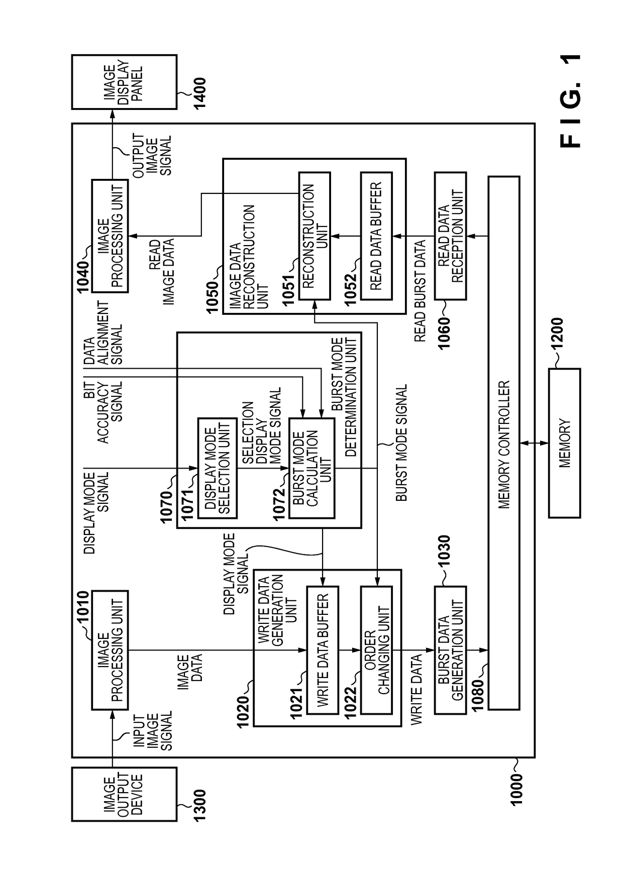
[0021]An example of the arrangement of an image processing apparatus 1000 according to this embodiment will be described first with reference to the block diagram of FIG. 1. An image output device 1300 supplies one image to the image processing apparatus 1000. The image output device 1300 can be any device which can provide images, for example, a memory device which holds images or an image sensing device which can sense a still image or movie. One image input from the image output device 1300 to the image processing apparatus 1000 may be one still image or each frame image constituting a movie. The image processing apparatus 1000 stores the image supplied from the image output device 1300 in a memory 1200 upon processing the supplied image, and outputs the processed image stored in the memory 1200 to an image display panel 1400 upon reading out and processing the image. Although FIG. 1 shows an example of the arrangement of the image processing apparatus 1000 including two image pr...

second embodiment

[0057]An example of the arrangement of an image processing apparatus 3000 according to this embodiment will be described with reference to the block diagram of FIG. 3. The same reference numerals as in FIG. 1 denote the same functional units in FIG. 3, and a description of the functional units will be omitted. Mainly differences from the first embodiment will be described below, and the other contents are the same as those in the first embodiment unless otherwise specified.

[0058]In this embodiment, as in the first embodiment, the burst length is 8, the burst data width is 32 bits, the image data format is RGB, the bit accuracy signal is 12 bits, and the data alignment signal indicates the total alignment scheme. Note that the maximum pixel count which can be stored in a total bit count of 256 corresponding to a burst length of 8 is 7 (252 bits). In this case, therefore, 4 padding bits are inserted.

[0059]An image analysis unit 3090 decides a display mode by analyzing the image proces...


PUM


Abstract

The order of the respective elements constituting image data is changed according to an order specified by a designated operation mode. The resultant data are transferred to a memory in a predetermined transfer unit. The respective elements constituting the data transferred to the memory are then processed after changing to the order before changing the order according to the above order.

Description

BACKGROUND OF THE INVENTION[0001]Field of the Invention[0002]The present invention relates to an image processing technique and, more particularly, to a technique of transferring image data.[0003]Description of the Related Art[0004]With recent advances in the resolution and image quality of display and projector products, image processing engines are required to perform complicated image processing at high speed. Such a requirement is mainly met by achieving higher integration and higher operating frequency with advances in semiconductor processes. However, an increase in the electromagnetic radiation of an LSI along with an increase in operating frequency makes it difficult to take countermeasures against EMI (Electro Magnetic Interference). EMI hinders the operations of other devices and affects the human body. It is therefore very important to suppress EMI within a reference value.[0005]As one of the countermeasures against EMI, a so-called SSCG (Spread Spectrum Clock Generator) ...

Claims


Application Information

Patent Timeline
Patent Type & Authority Patents(United States)
IPC IPC(8): G06T1/60G06F12/00
CPCG06T1/60G06F12/00
Inventor CHIDA, HIROMASA
Owner CANON KK
Why Eureka
Try Eureka