Liquid crystal display device, and timing controller and signal processing method used in same

a technology of liquid crystal display and timing controller, which is applied in the direction of electric digital data processing, instruments, computing, etc., can solve the problems of reference potential wiring noise, emi noises are also emitted from reference potential wiring, and above conventional technologies,

Active Publication Date: 2014-08-05
NEC LCD TECH CORP
View PDF15 Cites 1 Cited by
  • Summary
  • Abstract
  • Description
  • Claims
  • Application Information

AI Technical Summary

Benefits of technology

[0014]In view of the above, it is an object of the present invention to provide a liquid crystal display device, a timing controller and a signal processing method to be used in the liquid crystal display device in which EMI noises are reduced and miniaturization and thinning of a signal processing board are also achieved even if transmission of image data is speeded up.
[0025]With the above configurations, portions in which the superimposition of phases of clock signals corresponding to each display region can be reduced, whereby the EMI noises occurring in the reference potential wiring can be suppressed.

Problems solved by technology

Moreover, due to an insufficient area for a reference potential wiring (ground) caused by the miniaturization and thinning of a signal processing board, the EMI noises are also emitted from the reference potential wiring.
However, the above conventional technologies have the following problems.
The liquid crystal display device disclosed in the Patent Reference 2 has a problem in that, since the internal clock signals are frequency-divided into f / N, as shown in FIG. 13B, noises occur in the reference potential wiring.
As a result, superimposition of phases of signals having the same frequency occurs, which causes a larger noise peak and the above problems remain unsolved.

Method used


Image

  • Liquid crystal display device, and timing controller and signal processing method used in same
  • Liquid crystal display device, and timing controller and signal processing method used in same
  • Liquid crystal display device, and timing controller and signal processing method used in same

Examples


first exemplary embodiment

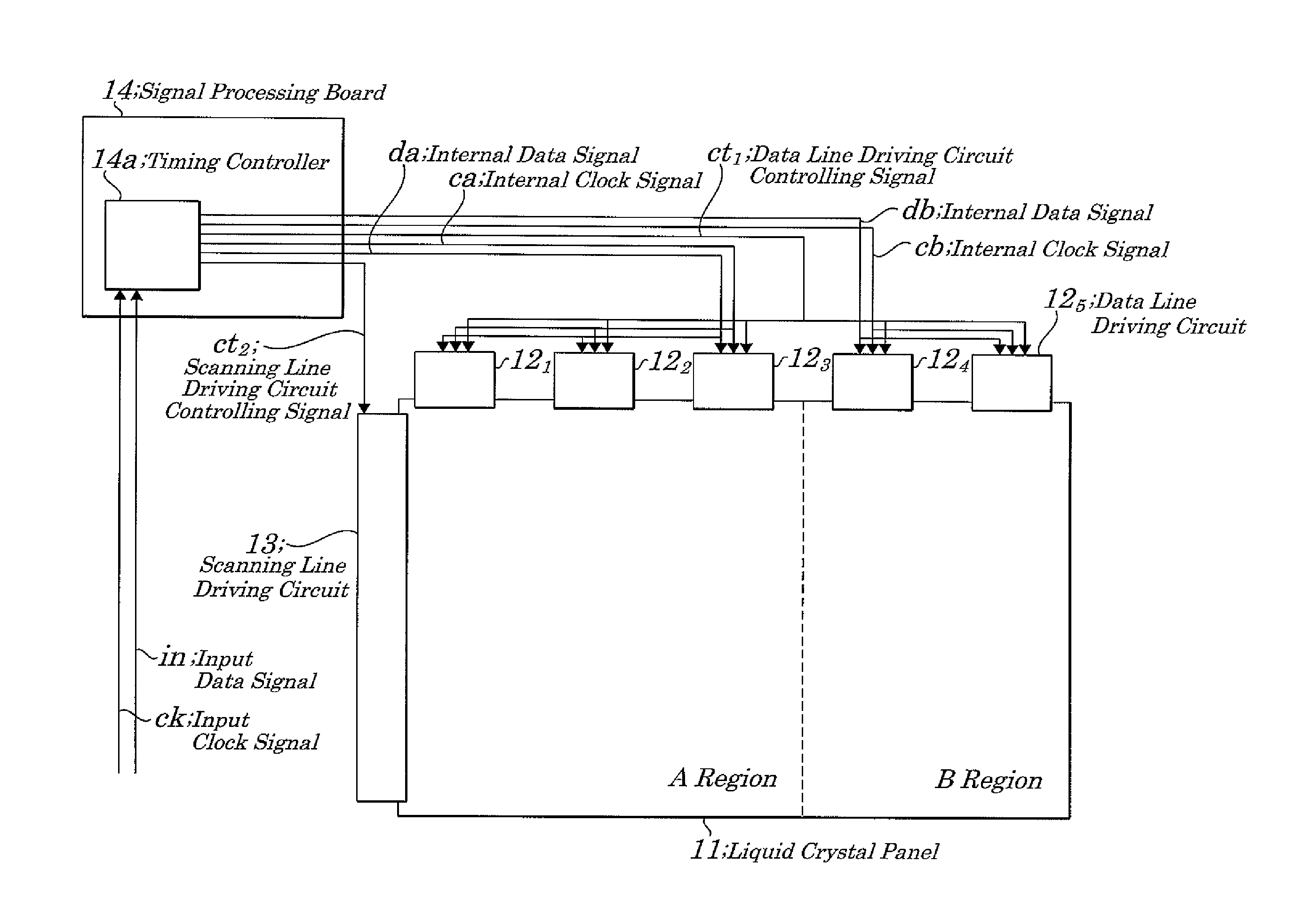
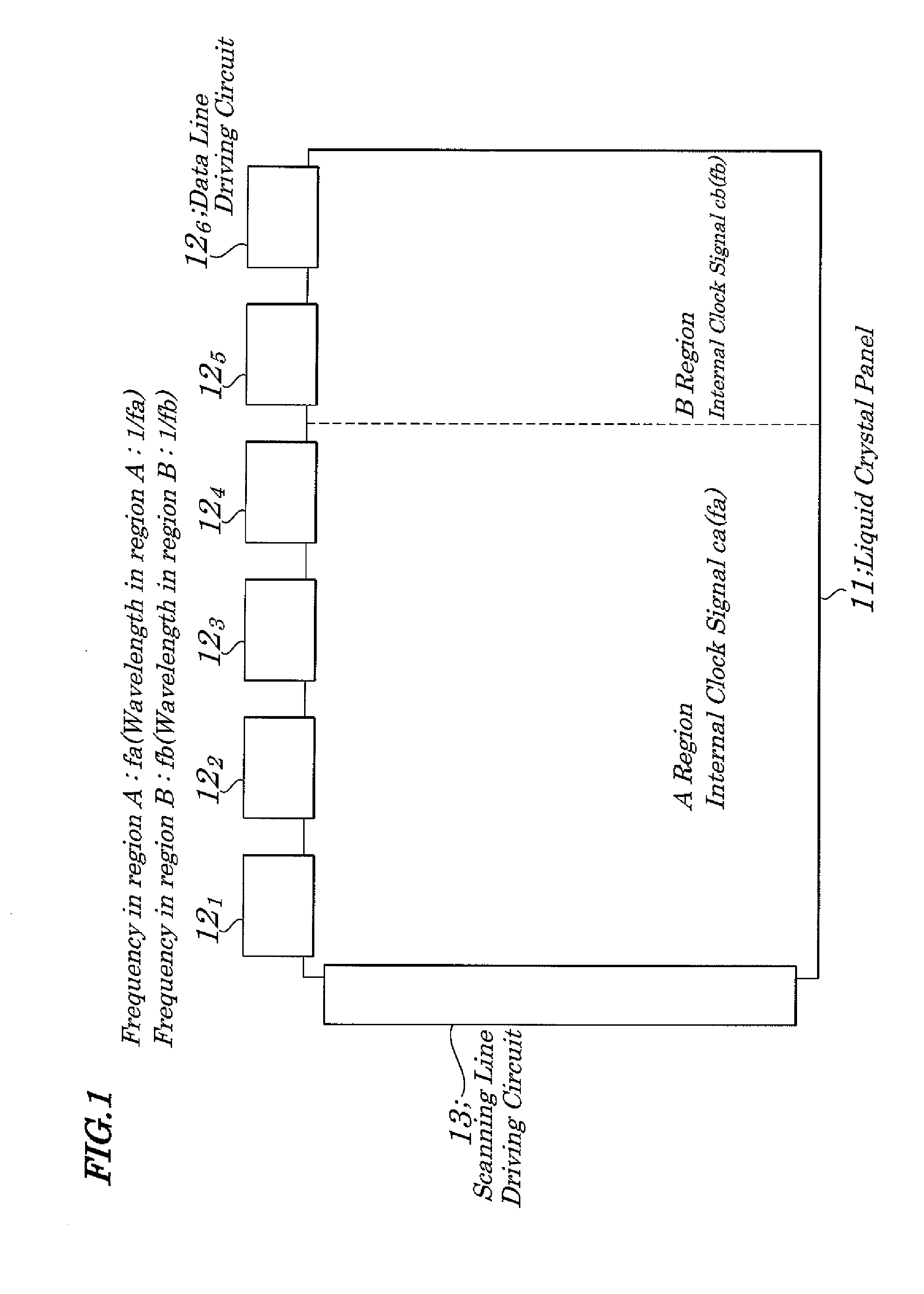
[0051]FIG. 5 is a block diagram showing electrical configurations of main portions of a liquid crystal display device of the first exemplary embodiment of the present invention. The liquid crystal display device of the first exemplary embodiment, as shown in FIG. 5, includes a liquid crystal panel 11, data line driving circuits 122, 122, . . . 125, a scanning line driving circuit 13, and a signal processing board 14. The liquid crystal panel 11 has predetermined columns of data lines (not shown), predetermined rows of scanning lines (not shown), and pixels each being mounted at the point of intersection of each of the data lines and scanning lines all of which makes up its display region. In the first exemplary embodiment, the display region of the liquid crystal panel 11 is divided, in a column direction, into two portions, regions A and B, in which the region B is smaller in area than the region A.

[0052]Each of the data line driving circuits 122, 122, . . . , 125, in accordance wi...

second exemplary embodiment

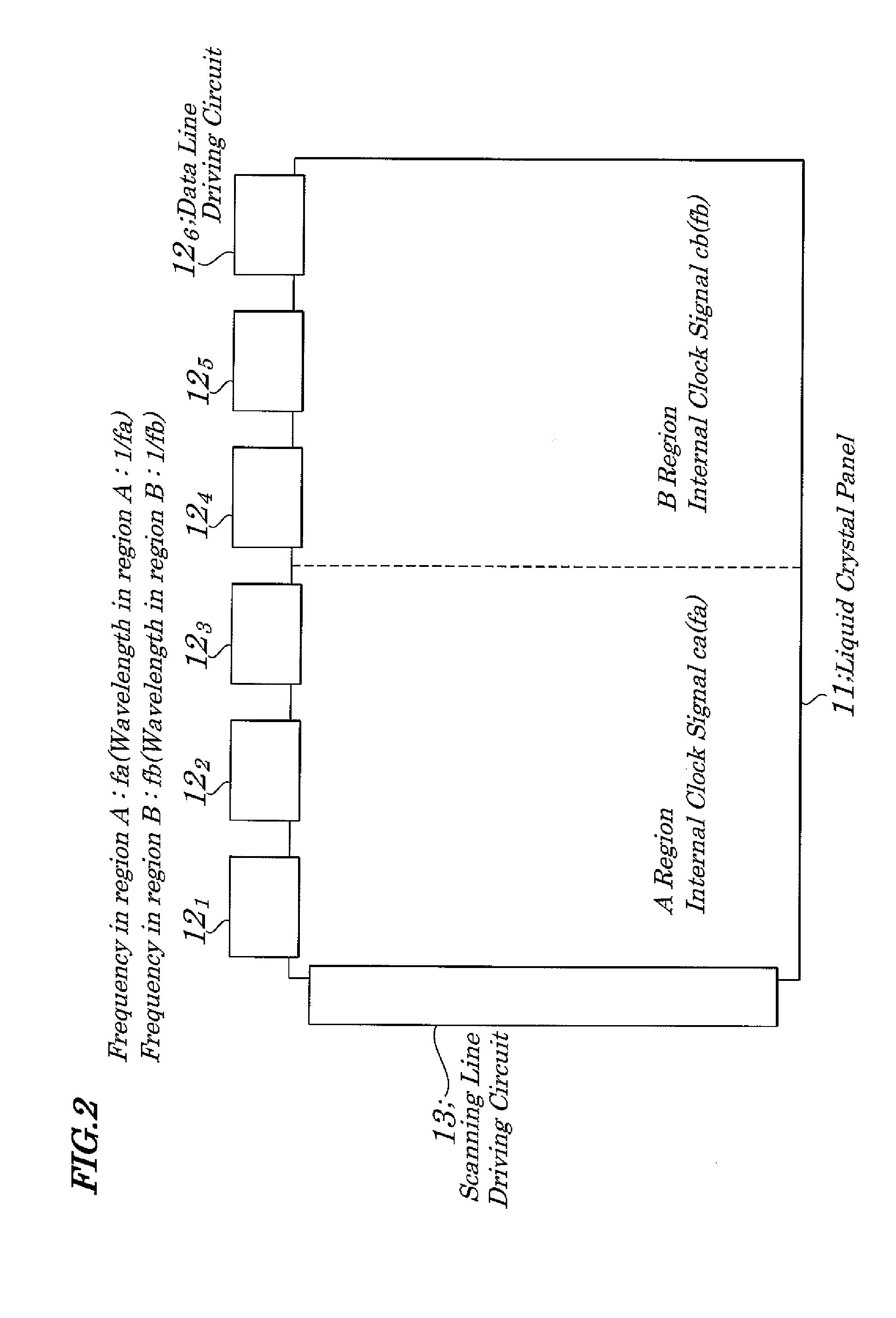
[0060]FIG. 11 is a block diagram showing electrical configurations of a liquid crystal display device of the second exemplary embodiment of the present invention. In the second exemplary embodiment, a display region of a liquid crystal panel 11 is divided, in a column direction, into two portions, regions Ae and Be, in which the region Ae is equal in area to the region Be. Data line driving circuits 121, 122, and 123 and data line driving circuits 124, 125, and 126 are mounted in a manner to be associated respectively with the regions Ae and Be. Instead of the signal processing board 14 (first exemplary embodiment) in FIG. 5, a signal processing board 14B having a different function is mounted. The signal processing board 14B has a timing controller 14e. The function of the timing controller 14e differs from that of a timing controller 14a (first exemplary embodiment) in that a wavelength of an internal clock signal cb out of internal clock signals ca and cb each corresponding to th...


PUM


Abstract

A liquid crystal display device is provided which is capable of reducing EMI (ElectraMagnetic Interference) noises while simultaneously responding to requirements for the high-speed transmission of image data, miniaturization and thinning of a signal processing board. A timing controller outputs, in accordance with an input data signal and input clock signal, a data line driving circuit controlling signal, internal data signal, internal clock signal to a data line driving circuit and outputs a scanning line driving circuit controlling signal to a scanning line driving circuit. The timing controller has a clock signal frequency setting mode in which a frequency of each of clock signals is set to a different value and the clock signals are supplied to the data line driving circuits and other data line driving circuits in one region and another region.

Description

INCORPORATION BY REFERENCE[0001]This application is based upon and claims the benefit of priority from Japanese Patent Application No. 2009-093471, filed on Apr. 7, 2009, the disclosure of which is incorporated herein in its entirely by reference.BACKGROUND OF THE INVENTION[0002]1. Field of the Invention[0003]The present invention relates to a liquid crystal display device, and a timing controller and a signal processing method to be used in the liquid crystal display device and more particularly to the liquid crystal display device capable of simultaneously achieving reduction of noises, miniaturization and thinning of a signal processing board, and high-speed transmission of image data, and to the timing controller and the signal processing method to be used in the liquid crystal display device.[0004]2. Description of the Related Art[0005]In a liquid crystal display device, EMI (ElectroMagnetic Interference) noises occur in some cases. The reasons for the EMI noises are as follows...

Claims


Application Information

Patent Timeline
Patent Type & Authority Patents(United States)
IPC IPC(8): G09G3/36
CPCG09G3/3648G09G3/3611G09G2300/0876G09G2310/08G09G2330/06G09G2370/08
Inventor OTA, SHINJI
Owner NEC LCD TECH CORP
Why Eureka
Try Eureka