Dc-dc converter system

a converter system and converter technology, applied in the direction of home appliance efficiency improvement, emergency protective circuit arrangement, sustainable buildings, etc., can solve the problems of limiting the output voltage of the dc-dc converter system, and achieve the effect of reducing noise, switching noise, and increasing the heating of the power switching devi

Inactive Publication Date: 2008-09-04
TOYOTA JIDOSHA KK +1
View PDF5 Cites 34 Cited by
  • Summary
  • Abstract
  • Description
  • Claims
  • Application Information

AI Technical Summary

Benefits of technology

[0021]That is, the switching frequency of the power switching device at the time of the overheat temperature state is reduced from that at the time of the normal temperature state, for example, by a few tenths. The power switching device of the DC-DC converter system is controlled, for example, by PWM feedback control. Normally, in order to reduce noises, switching noise voltage, an output current ripple, etc., the power switching device is operated at a frequency of a few hundreds kHz to a few MHz. However, when the switching frequency is high, a transient loss, namely an on-off loss of the power switching device of the DC-DC converter increases and heating of the power switching device increases. Therefore, considering that it is more important to secure power supply from the DC-DC converter to the load system than solving problems of the noises, switching noise voltage, etc. in the overheat temperature state, electric power is supplied while reducing the switching frequency of the power switching device. This arrangement makes it possible to maintain stable power supply to the load system while heating is inhibited in the overheat temperature state in the vicinity of the stop temperature.

Problems solved by technology

That is, the DC-DC converter system limits the output voltage in addition to conventional limitation of the output current in the overheat temperature state in the vicinity of the operation stop temperature.

Method used


Image

  • Dc-dc converter system
  • Dc-dc converter system
  • Dc-dc converter system

Examples


Embodiment Construction

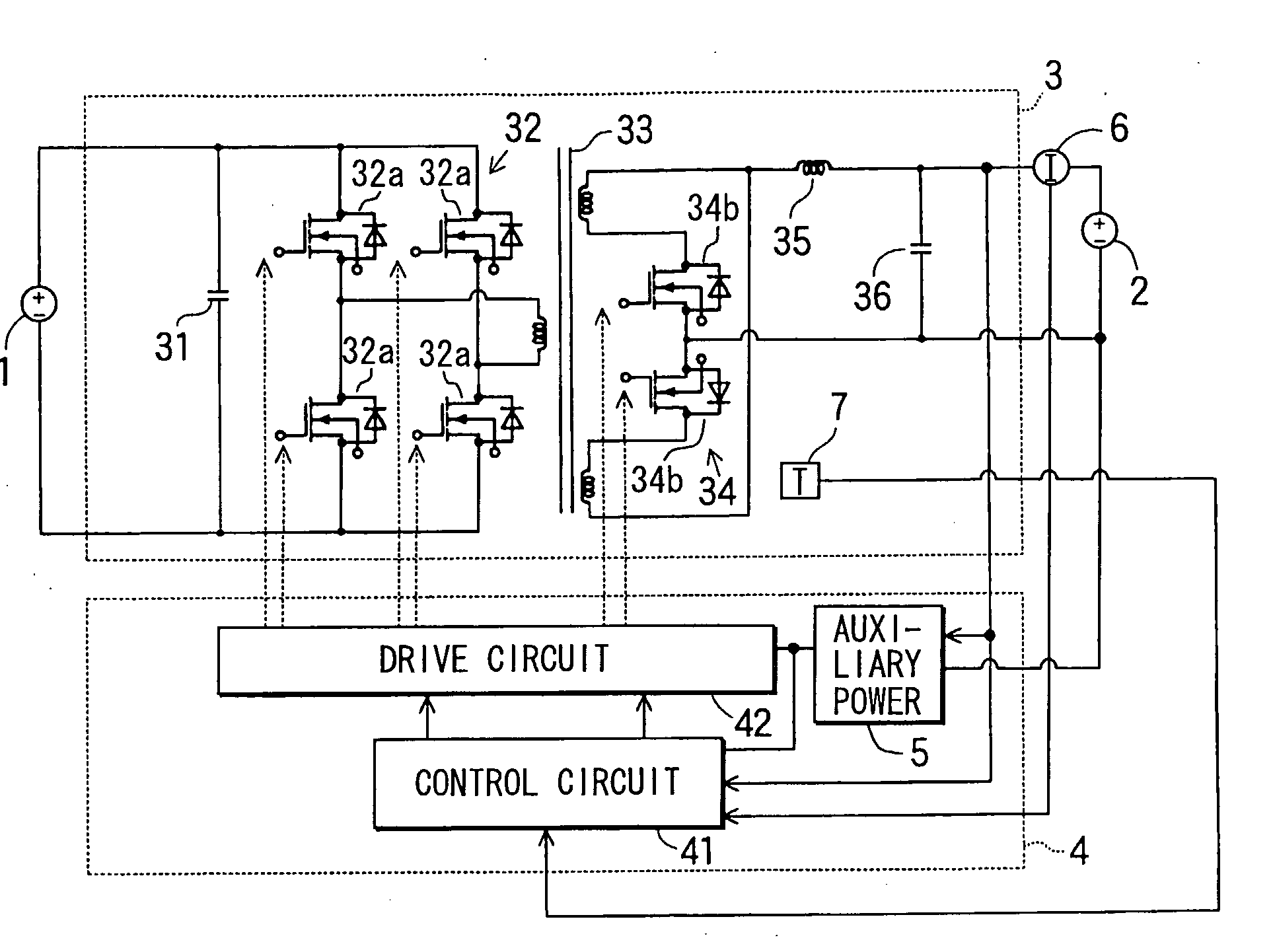
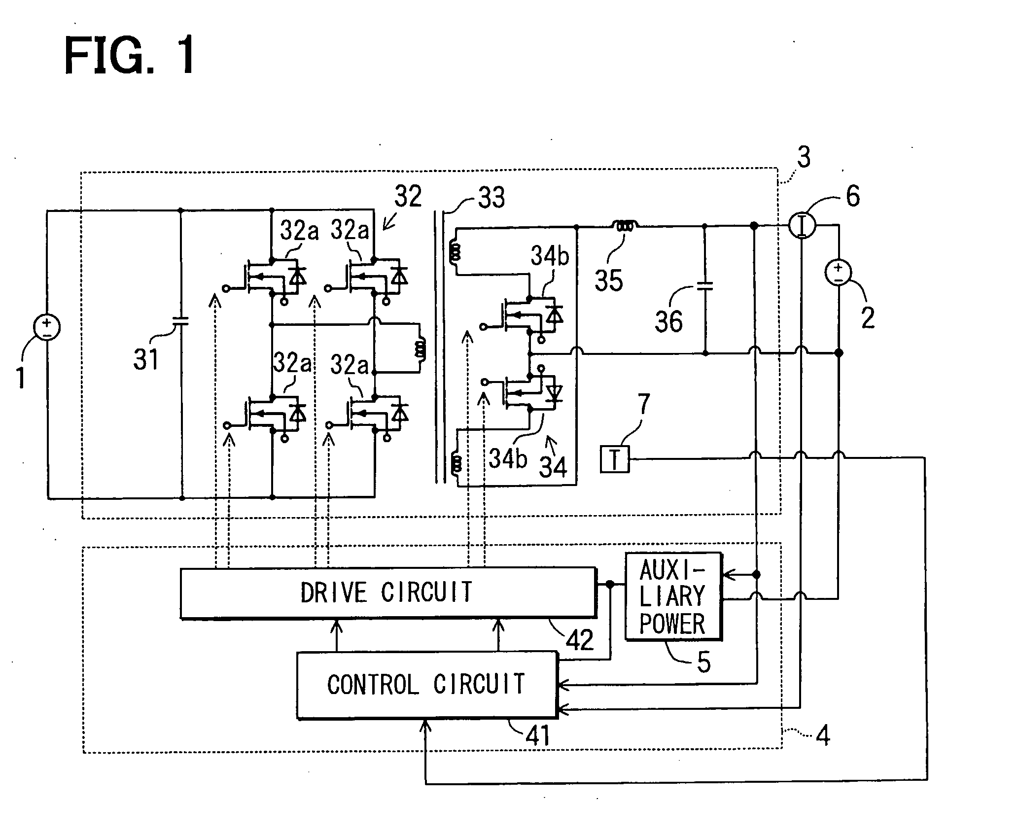
[0026]A DC-DC converter system is applied to a dual-battery type vehicular power supply system in a preferred embodiment as shown in FIG. 1.

[0027]This dual-battery type vehicular power supply system is connected to a main battery 1 and an auxiliary battery 2, and has a battery charging DC-DC converter 3, a DC-DC converter control circuit unit 4 for controlling a switching operation of this battery charging DC-DC converter 3. This power supply system is constructed to supply electric power to an electronic controller (not shown) from the main battery 1 for charging traction energy of a hybrid vehicle after transforming its voltage and to supply electric power to auxiliary or accessory devices and the auxiliary battery 2 for an auxiliary purpose. The power supply system is also connected to a current sensor 6 and a temperature sensor 7.

[0028]The DC-DC converter 3 for battery charging adopts a well-known circuit configuration comprised of an input smoothing capacitor 31, an inverter ci...


PUM


Abstract

A DC-DC converter system is provided to improve switching control operation of a battery charging DC-DC converter (3) in an overheat temperature state without necessitating complication of a control unit (4). The control unit (4) performs output voltage limitation as well as output current limitation when the temperature of the DC-DC converter (3) is in an overheat temperature state in the vicinity of its operation stop temperature. With this capability, the output current and the output voltage can be limited, and therefore overheating of a power switching device (32) of the DC-DC converter (3) can be inhibited. In an alternative embodiment the switching frequency of the power switching device (32) is limited.

Description

TECHNICAL FIELD[0001]This invention relates to a DC-DC converter system that supplies an output from a direct current power supply source by converting by means of switching of a built-in power switching device to an electric load system.[0002]This application is based on and incorporates herein by reference Japanese Patent Application No. 2005-87004 filed on Mar. 24, 2005.BACKGROUND ART[0003]For vehicular power supply systems of hybrid vehicles and idle-stop vehicles, dual-battery type vehicular power supply systems are proposed. In this unit, two batteries having different supply voltages are used for a vehicular power supply system. Further, a high voltage battery of a few tens or hundreds volts supplies power to large electric power loads, while a low voltage battery of over ten volts, such as a lead battery, supplies power to low power electric loads. The high voltage battery is charged by a power generating set of a high voltage. The low voltage battery or a low voltage load c...

Claims


Application Information

Patent Timeline
Patent Type & Authority Applications(United States)
IPC IPC(8): H02H7/10H02M1/00
CPCH02J7/047H02M1/32Y02B40/90Y02B70/1475H02M3/33592H02J7/007192Y02B70/10H02J7/04Y02B40/00
Inventor YAMASHITA, TSUYOSHITODA, MAMORUOTSUKA, KENJI
Owner TOYOTA JIDOSHA KK
Why Eureka
Try Eureka