Power electronic module IGBT protection method and system

a technology of power electronic modules and protection methods, applied in the direction of motor/generator/converter stoppers, dynamo-electric converter control, pulse techniques, etc., can solve the problems of increasing the rate of igbt failure, increasing mechanical stress, and techniques that have not been able to account for the increase of stress

a technology of power electronic modules and protection methods, applied in the direction of motor/generator/converter stoppers, dynamo-electric converter control, pulse techniques, etc., can solve the problems of increasing the rate of igbt failure, increasing mechanical stress, and techniques that have not been able to account for the increase of stress

US20100080024A1Active Publication Date: 2010-04-01ROCKWELL AUTOMATION TECH

Image

  • Power electronic module IGBT protection method and system
  • Power electronic module IGBT protection method and system
  • Power electronic module IGBT protection method and system

Examples


Embodiment Construction

[0014]Embodiments of the present invention relate to reducing the mechanical stress on IGBTs due to large temperature variations of the junction. Large junction temperature variations may contribute to particularly high levels of mechanical stress, because the different expansion rates of the various materials inside the IGBT package may lead to wire crack growth in wire bonds and similar contacts. Therefore, reducing junction temperature variations may result in a longer lasting inverter module. In embodiments of the present invention, the junction temperature variation is controlled by controlling the switching frequency. Because the highest junction temperature variations tend to occur during start-up or low-speed, high-current conditions, the switching frequency may be reduced for only a short time during start-up, after which the switching frequency may be increased to provide a smoother sinusoidal waveform.

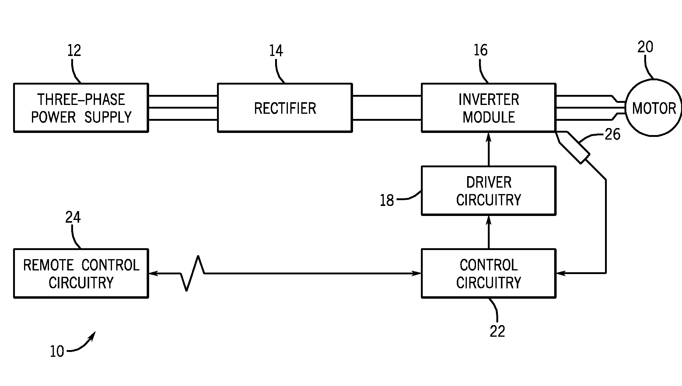
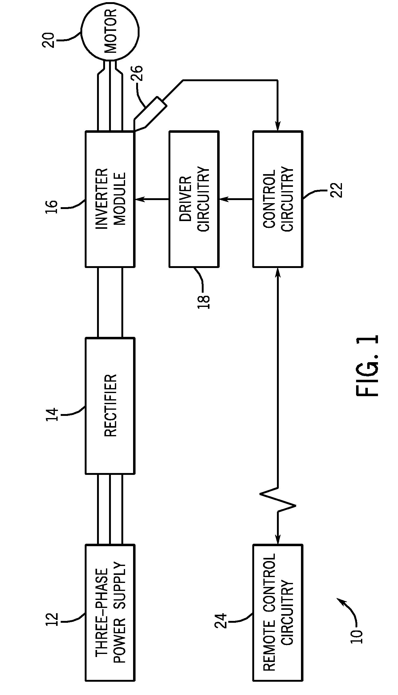
[0015]FIG. 1 illustrates an exemplary motor control system 10 employing...


PUM


Abstract

A power electronics device with an improved IGBT protection mechanism is provided. More specifically, systems and methods are provided for reducing the switching frequency of an inverter module based on the junction temperature variation of the IGBT.

Description

BACKGROUND[0001]The invention relates generally to the field of electrical power converters and inverters. More particularly, the invention relates to techniques for preventing failure of motor drive circuitry due to overheating.[0002]Power inverters and converters typically employ power modules to create a desired output current waveform, which is used to power various devices, such as motors and other equipment. The frequency and amplitude of the output current waveform may effect the operation of the device such as by changing the speed or torque of a motor, for example. Some power modules create the desired output current waveform through pulse width modulation, wherein power semiconductor switches such as insulated gate bipolar transistors (IGBTs) are caused to switch rapidly on and off in a particular sequence so as to create an approximately sinusoidal output current waveform. Furthermore, high IGBT switching speeds tend to produce a smoother, more ideal sinusoidal waveform, ...

Claims


Application Information

Patent Timeline
01 Apr 2010
Publication
US20100080024A1
IPC
H02M7/537
CPC
H02M1/32; H03K2017/0806; H03K17/0828
Inventors
WEI, LIXIANG; TSUYOSHI, MASAHIRO