
Autostereoscopic 3D display device using holographic optical elements

A holographic optical element and auto-stereoscopic technology, applied in optical elements, optics, electrical elements, etc., can solve problems such as difficulty in accurately producing 3D films and increase in size of 3D display devices

Active Publication Date: 2021-03-12
COVESTRO DEUTSCHLAND AG
View PDF5 Cites 0 Cited by
  • Summary
  • Abstract
  • Description
  • Claims
  • Application Information

AI Technical Summary

Problems solved by technology

However, the use of lenses or mirrors may lead to an increase in the size of the 3D display device
In the case of 3D films with prisms, it can be difficult to accurately produce micron-sized 3D films with prisms and to accurately align the 3D films with prisms to light guiding structures

Method used


Image

  • Autostereoscopic 3D display device using holographic optical elements
  • Autostereoscopic 3D display device using holographic optical elements
  • Autostereoscopic 3D display device using holographic optical elements

Examples


Embodiment Construction

[0035] Reference will now be made in detail to various embodiments, examples of which are illustrated in the accompanying drawings. In the following Detailed Description, numerous specific details are set forth in order to provide a thorough understanding of the inventive aspects of the present disclosure. It will be apparent, however, to one skilled in the art that the inventive aspects of the present disclosure may be practiced without these specific details. In other instances, well-known methods, procedures, systems, and components have not been described in detail so as not to unnecessarily obscure aspects of the various embodiments.

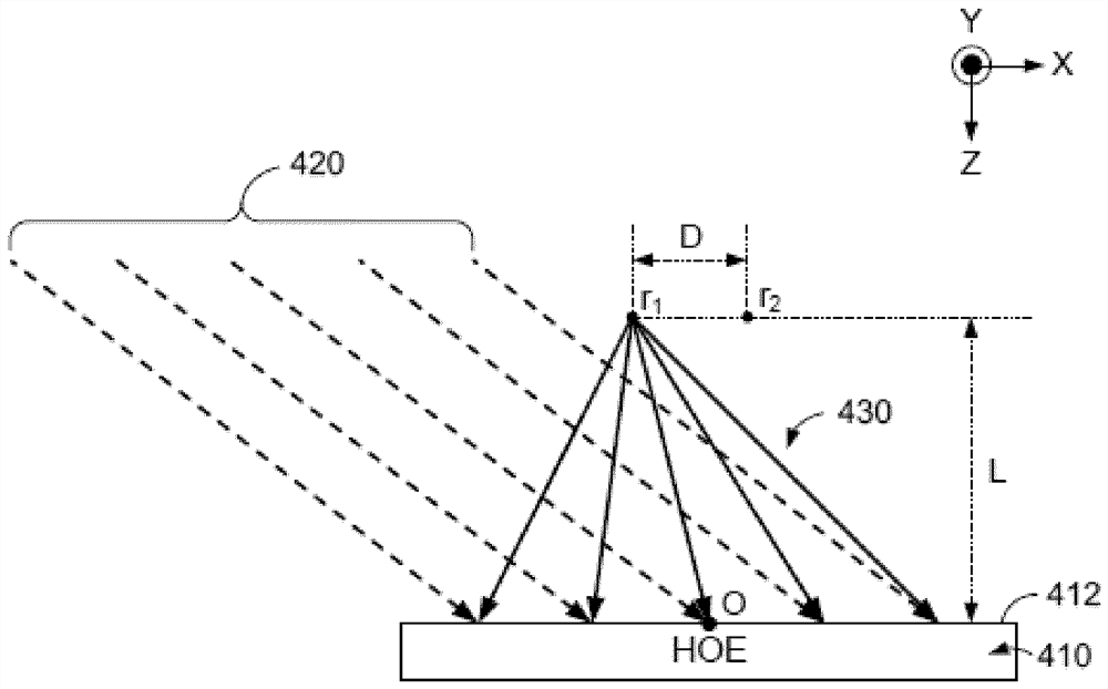
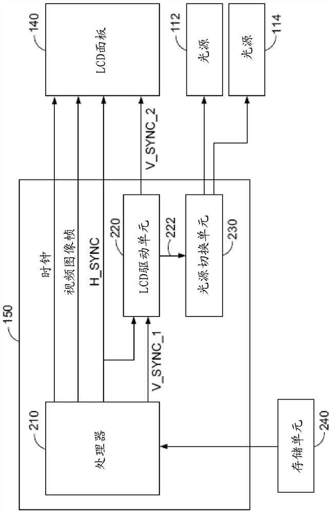
[0036] figure 1 Illustrated is an autostereoscopic 3D display device 100 configured to project a pair of stereoscopic images displayed on an LCD panel 140 , which may be perceived as 3D images by a viewer 190 , according to one embodiment of the present disclosure. The autostereoscopic 3D display device 100 includes a pair of light source...


PUM


Abstract

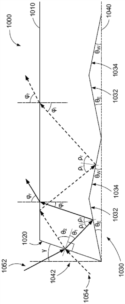
An autostereoscopic 3D display device (100) is disclosed. The device includes: a first light source (112) and a second light source (114) configured to alternately generate light (162, 164); and a light guide plate (120) arranged to direct light from the first light source in Light from a second light source is directed in a first direction as a first light beam (172) and in a second direction as a second light beam (174). In the device, a stack (130) of a plurality of holographic optical elements is configured to converge the first light beam and the second light beam from the light guide plate. The stack of multiple holographic optical elements may comprise at least one first holographic optical element (132) and at least one second holographic optical element (134). The light guide plate includes prismatic structures configured to reflect light from the first and second light sources towards a light guide plate surface (1010) of the stack adjacent to the holographic optical element. The prism structure includes at least one first bevel (1032) with a first inclination angle and at least one second bevel (1034) with a second inclination angle, wherein the first and second inclination angles are less than 10°.

Description

technical field [0001] The present disclosure relates to autostereoscopic 3D display devices, and more particularly to autostereoscopic 3D display devices using multiple holographic optical elements (HOEs). Background technique [0002] In recent years, 3D displays for viewing three-dimensional (3D) images have become popular. For example, a movie theater equipped with a 3D display or 3D television may allow viewers to watch 3D movies for an enhanced viewing experience. However, such 3D movies often require viewers to wear 3D glasses or visual aids to perceive the 3D images. The use of such 3D glasses or vision aids may be cumbersome to some viewers due to the weight or discomfort of the devices. [0003] In order to alleviate such inconvenience for viewers, autostereoscopic displays that allow viewers to perceive 3D images without 3D glasses or visual aids have been developed. Conventional autostereoscopic displays usually display 3D images using a spatial multiplexing m...

Claims


Application Information

Patent Timeline
Patent Type & Authority Patents(China)
IPC IPC(8): G02B30/33G02B30/36G02B5/32F21V8/00G02B30/26
CPCG02B5/32G02B6/0036H04N13/32H04N13/39G02B30/26
Inventor F-K.布鲁德R.哈根T.法伊克G.瓦尔策E.S.金Y.S.黄
Owner COVESTRO DEUTSCHLAND AG
Learn More