Mount with hidden magnetically actuated positioning

A technology of magnetic components and fasteners, applied in the field of positioning systems, can solve problems such as boring

Active Publication Date: 2017-02-22
PLANAR SYSTEMS
View PDF6 Cites 35 Cited by
  • Summary
  • Abstract
  • Description
  • Claims
  • Application Information

AI Technical Summary

Problems solved by technology

Prior art mounting systems provide some adjustment of the position of the display portion, but such adjustments are tedious and often require multiple iterative adjustments of the display panel portion

Method used


Image

  • Mount with hidden magnetically actuated positioning
  • Mount with hidden magnetically actuated positioning
  • Mount with hidden magnetically actuated positioning

Examples


Embodiment Construction

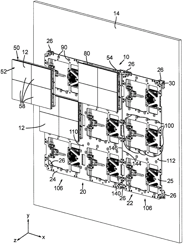
[0017] figure 1 An arrangement of an electronic image display device 10 comprising a regular array of display panel sections 12 is shown. The display device 10 is secured to a wall 14 in the form of a backing plate and alternatively comprises a frame or open studs or other support structure. The wall 14 or other support structure is preferably flat, but may be sloped or angled or curved. Mounting plate assemblies 20 and 22 (also referred to as mounting brackets or mounting platforms) are secured to wall 14 . Mounting plate assemblies 20 and 22 form a support platform comprised of one or more support sections 24 , 25 . Each mounting plate assembly 20 and 22 includes a plurality of corner mounts 26 that attach each of the support sections 24 , 25 to the wall 14 using screws or other fasteners.

[0018] Each corner mount 26 includes an adjustable standoff screw 30 , such as a jack screw, that adjustably connects the corner mount 26 to its corresponding support portion, such as...


PUM


Abstract

A mounting and leveling system for an electronic image display device (10) formed of an array of multiple display sections (12) facilitates adjustment of the alignment of adjacent display sections to minimize visible seams between display sections. Some embodiments include one or more magnetically actuated fasteners (220) that facilitate front-access-only installation and adjustment without requiring access to the rear, top, bottom, or sides of the array. Tools (300, 410) for installation and removal of display modules (50) from a front side of the display device are also disclosed. Fasteners (220) for providing a hidden adjustable connection between first and second objects are also disclosed. One such fastener includes a screw (226) having a magnetic head (222) that presents a magnetic moment perpendicular to its axis of rotation (234).

Description

[0001] related application [0002] This application claims the benefit under 35 U.S.C § 119(e) of U.S. Provisional Patent Application 62 / 097,539, filed December 29, 2014, and U.S. Provisional Patent Application 62 / 114,021, filed February 9, 2015, both of which patent applications are incorporated herein by reference. technical field [0003] The present disclosure relates to positioning systems for arrays of electronic image display panels (e.g., direct-view LED display panels), and more particularly to concealment systems that include operable from outside the front surface of the array of display panels to adjust the position and relative alignment of the panels. Positioning system for magnetic fasteners. Background technique [0004] Mounting and positioning systems known in the art often assemble multiple display panels or display panel sections into regular arrays for larger displays, wherein video or images are displayed across the multiple display panel sections. E...

Claims


Application Information

Patent Timeline
Patent Type & Authority Applications(China)
IPC IPC(8): G09F9/302
CPCG09F9/3026F16M11/041F16M11/121F16M11/18F16M13/02G09G2300/026F16B2200/83B25B23/12B25B27/14E05B47/004E05B47/0045F16B1/00F16B5/02F16K31/088F16M13/022F21V21/34G06F3/1446G09F9/33G09G3/30H01F7/0252H05K5/0021H05K7/1427
Inventor N·布拉斯奈克T·洛伊E·斯舒特克
Owner PLANAR SYSTEMS
Why Eureka
Try Eureka